
Device of evaluating magnetic read head and method of evaluating magnetic read head

a magnetic read and read head technology, applied in the field of evaluating magnetic read heads, can solve the problems of difficult to obtain the accurate coercive force the measurement time of the gazette is long, etc., and achieves the effect of simple evaluation of the magnetic bias layer, short time and high precision

Inactive Publication Date: 2011-08-02
TDK CORPARATION
View PDF4 Cites 13 Cited by
  • Summary
  • Abstract
  • Description
  • Claims
  • Application Information

AI Technical Summary

Benefits of technology

This approach allows for the accurate and efficient evaluation of magnetic characteristics, such as coercive force and squareness ratio, of the magnetic bias layer, improving reading performance by providing a more reliable method for determining the bias magnetic field with high reproducibility and precision.

Problems solved by technology

However, the method of the above-mentioned Japanese Patent No. 3877386 gazette requires a long time for measurement.
Moreover, when the magnetic shielding layer in the thin film magnetic head to be measured is magnetically unsaturated, it is difficult to obtain the coercive force of the magnetic bias layer accurately.

Method used


Image

  • Device of evaluating magnetic read head and method of evaluating magnetic read head
  • Device of evaluating magnetic read head and method of evaluating magnetic read head
  • Device of evaluating magnetic read head and method of evaluating magnetic read head

Examples


experimental example 2

[0082]Next, the hysteresis loop was repeatedly measured three more times for the sample of the magnetic read head evaluated in the experimental example 1-2 (four times in total) to investigate fluctuation in the measured value. The result is represented in FIG. 7. As represented in FIG. 7, the four hysteresis loops were approximately overlapped each other in the present Experimental Example, and good reproducibility was obtained.

[0083]Thus, according to the present invention, it is confirmed that determination on quality of the magnetic characteristics of the magnetic bias layers can be conducted promptly and correctly.

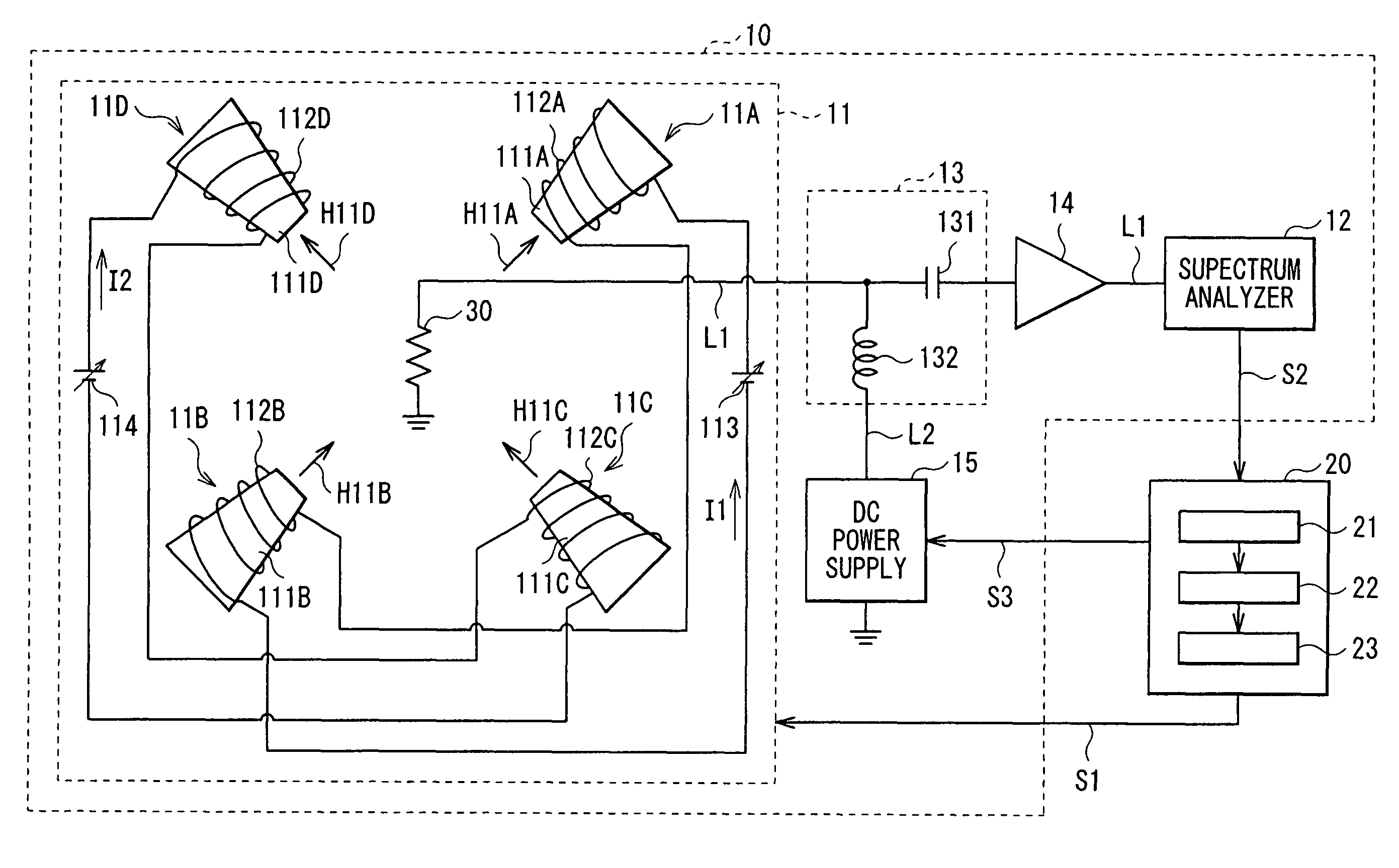
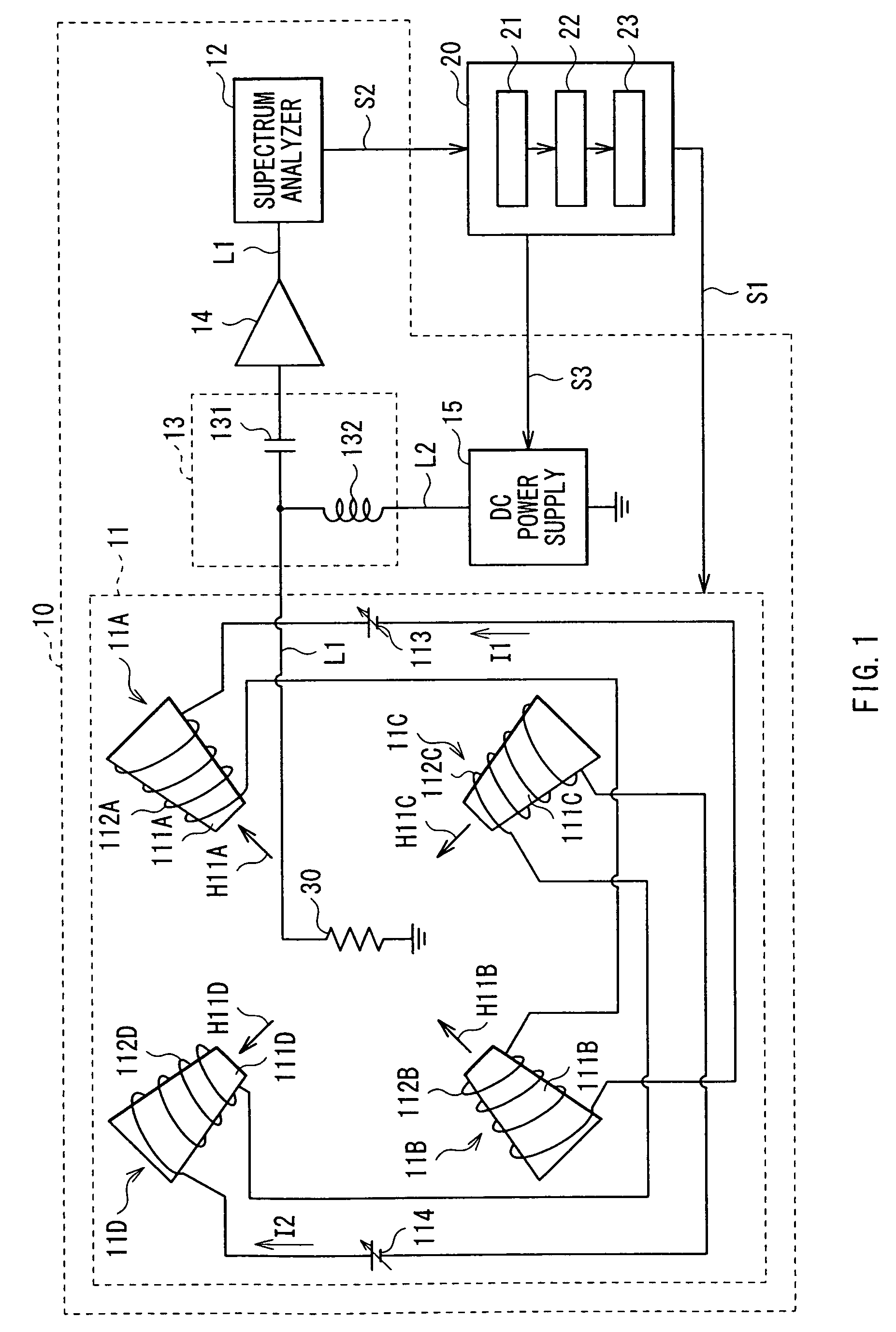
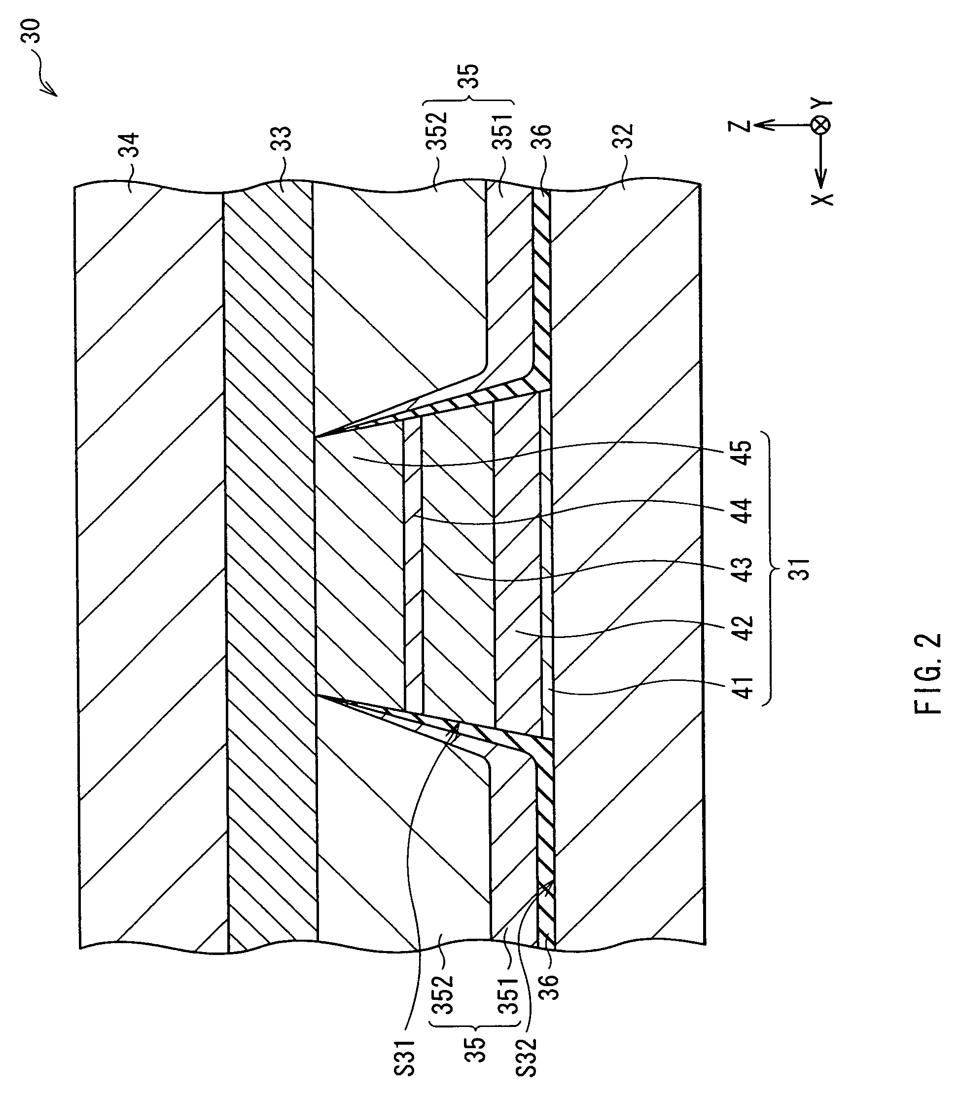
[0084]Association of reference numerals and component elements in the present embodiment is indicated below.

[0085]10: measuring section, 11: magnetic field application section, 12: spectrum analyzer, 13: waveform formation section, 14: amplifier, 15: DC power supply, 20: control unit, 21: data storing section, 22: operation section, 23: output section, 30: magnetic re...


PUM


Abstract

An MR element having a magnetically free layer and a magnetic bias layer that applies a bias magnetic field to the magnetically free layer are included. Furthermore, a measuring section that measures a ferromagnetic resonance frequency f0 of the magnetically free layer under a condition of applying a predetermined external magnetic field Hm to the magnetically free layer, and an operation section that computes the bias magnetic field Hb according to a following conditional expression (1):Hb={(2*π*f0 / γ)2 / Ms}−(Hk+Hm)  (1)where γ is a gyroscope constant, Ms is a saturation magnetic field of the magnetically free layer, and Hk is a shape anisotropy magnetic field of the magnetically free layer.

Description

BACKGROUND OF THE INVENTION[0001]1. Field of the Invention[0002]The present invention relates to a device of evaluating magnetic read head that includes a magnetoresistive element and to a method of evaluating the magnetic read head.[0003]2. Description of the Related Art[0004]A thin film magnetic head, which includes an MR element exhibiting magnetoresistive (MR: Magneto-resistive) effect, is widely used in the past for reading out information written on magnetic recording media such as a hard disk. Recently, a thin film magnetic head utilizing a giant magnetoresistive element (GMR element) that exhibits giant magnetoresistive (GMR: Giant Magneto-resistive) effect is used more generally because of increasing recording density of magnetic recording media. Examples of such GMR element include a spin valve (SV: spin valve) GMR element.[0005]The SV-GMR element has a structure in which a magnetic layer whose magnetization direction is fixed in a given direction (magnetically pinned laye...

Claims


Application Information

Patent Timeline
Patent Type & Authority Patents(United States)
IPC IPC(8): G01R33/12
CPCB82Y10/00B82Y25/00G11B5/3909G11B5/3932G11B5/455G11B2005/3996
Inventor ANTOKU, YOSUKE
Owner TDK CORPARATION
Learn More