
Sensor for identifying at least one particle by means of raman-spectroscopy

a technology of raman-spectroscopy and sensors, which is applied in the direction of spectrometry/spectrophotometry/monochromators, instruments, optical radiation measurement, etc., can solve the problems of experimental setup and unsuitable wide-spread use of sensors, and achieve the effect of facilitating the integration and miniaturization of sensors

Inactive Publication Date: 2011-07-19
TECH UNIV DELFT +1
View PDF6 Cites 2 Cited by
  • Summary
  • Abstract
  • Description
  • Claims
  • Application Information

AI Technical Summary

Benefits of technology

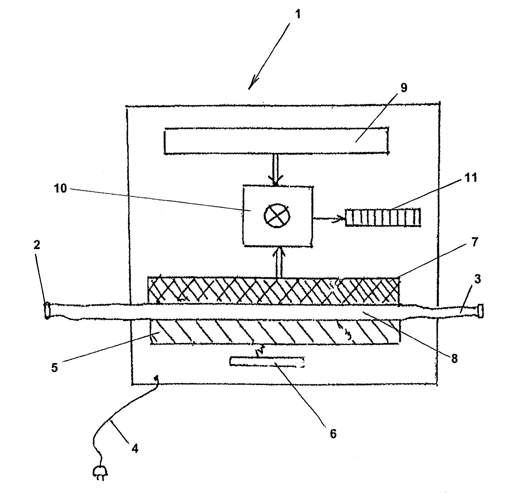
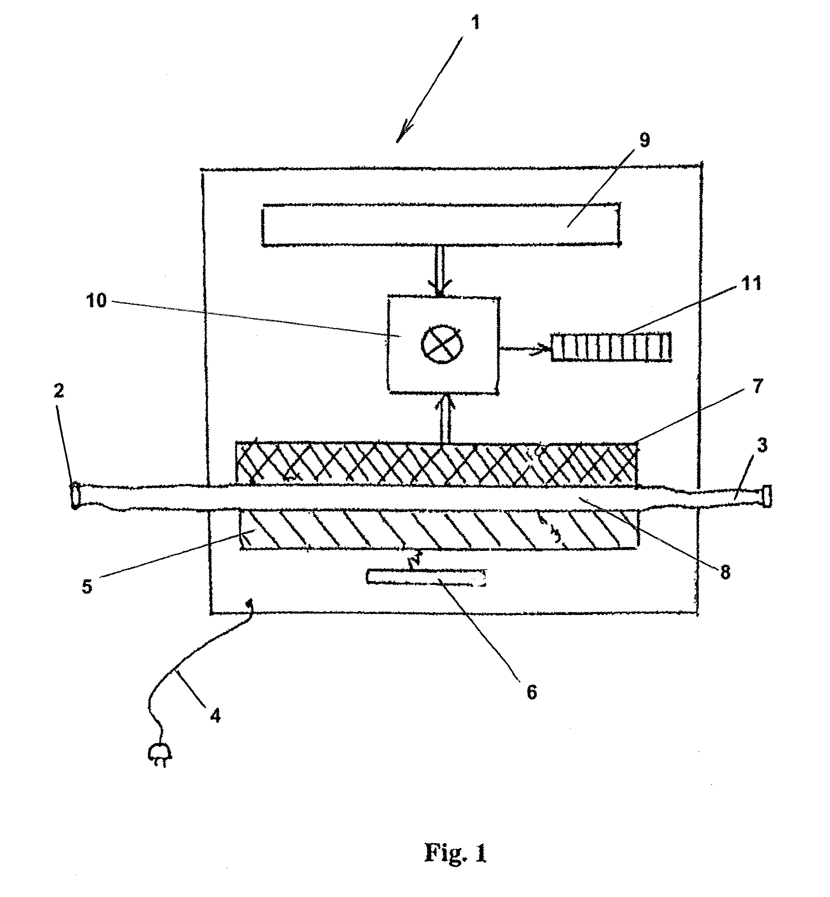
[0015]In this way the sensor is very suitable for use at a selected site providing as it were a laboratory on a chip, particularly when in the preferred situation the laser-beam source is selected to be at least one semi-conductor laser, and the photonic crystal is made of a material that is compatible with the semi-conductor material of said laser. This facilitates the integration and miniaturization of the sensor of the invention.DETAILED DESCRIPTION OF THE INVENTION
[0016]It is remarked that US-A1-2006 / 119853 relates to Raman spectroscopy, in particular surface enhanced Raman spectroscopy (“SERS”). This document teaches the use of a thin metal film deposited on a dielectric substrate patterned in the form of a photonic crystal to extract a SERS-signal from low concentrations of analyte molecules embedded inside the photonic crystal lattice, therewith enhancing the Raman-signal.
[0018]It is preferred that the walls of the fluid channel are at a distance which is smaller than approximately twice the particles' diameter. A doubled efficiency can be obtained with a design that is based on a photonic crystal membrane that acts as a central wall of a fluidic system, with separate Raman spectrometers for measurement of the emitted spectrum on opposite sides thereof.
[0019]It is further preferable that the laser source and / or the photonic crystal is switchable between an on-position and an off-position. When the laser and the photonic crystal are in the on-position, the at least one particle can become trapped and Raman-excited, whereas when the laser source or the photonic crystal is subsequently placed in the off-position the at least one particle is released so as to allow it to continue with the flow of the fluid going through the device. A quasi-continuous operation is then possible as opposed to single-shot operation. Equivalently one could add further optical or electrical means to execute the switching of the light beam to and away from the cavities for trapping and Raman exciting.

Problems solved by technology

Although according to the article a rapid identification of single bacterial cells in an aqueous solution is possible, the sensor set up used therefore was experimental and not suited for wide spread use at distributed places throughout the world at which monitoring for harmful particles is a continuous need.

Method used


Image

  • Sensor for identifying at least one particle by means of raman-spectroscopy
  • Sensor for identifying at least one particle by means of raman-spectroscopy

Examples


Embodiment Construction

[0016]It is remarked that US-A1-2006 / 119853 relates to Raman spectroscopy, in particular surface enhanced Raman spectroscopy (“SERS”). This document teaches the use of a thin metal film deposited on a dielectric substrate patterned in the form of a photonic crystal to extract a SERS-signal from low concentrations of analyte molecules embedded inside the photonic crystal lattice, therewith enhancing the Raman-signal.

[0017]The beauty of the invention is however that the photonic crystal has cavities that act both as trapping units for the particles to be identified, as well as means for providing Raman-excitation to said particles without the need to apply and excite a metal's surface or a metalloelectric film on a substrate's surface. The energy required herefore stems from the laser-beam source that is directly linked to the photonic crystal and that resonantly excites electromagnetic modes of the cavities of the photonic crystal. Through the use of multiple cavities the chance of a...


PUM


Abstract

A sensor for identifying at least one particle by means of Raman-spectroscopy, comprising an optical trapping system for the at least one particle, including a laser-beam source, acting further as a Raman excitation source for the at least one particle, and a Raman-spectrometer for measuring the spectrally modified light scattered by the at least one particle and for identifying same, wherein the optical trapping system comprises a photonic crystal directly linked with the laser-beam source, which photonic crystal has multiple cavities at predetermined positions, and wherein the laser-beam source in use resonantly excites one or more predetermined electromagnetic modes of the cavities at said positions for trapping and Raman-exciting the at least one particle.

Description

[0001]This application is a continuation-in-part application of international Patent Application Serial No. PCT / EP2008 / 055860, entitled “Sensor for Identifying at Least One Particle by Means of Raman-Spectroscopy”, to Technische Universiteit Delft, KIWA Water Research B.V. and 2M Engineering Ltd., filed on May 13, 2008, and the specification and claims thereof are incorporated herein by reference.[0002]This application claims priority to and the benefit of the filing of European Patent Application Serial No. 07108065.9, entitled “Sensor for identifying at least one particle by means of raman-spectroscopy”, filed on May 11, 2007, and the specification and claims thereof are incorporated herein by reference.STATEMENT REGARDING FEDERALLY SPONSORED RESEARCH OR DEVELOPMENT[0003]Not Applicable.INCORPORATION BY REFERENCE OF MATERIAL SUBMITTED ON A COMPACT DISC[0004]Not Applicable.COPYRIGHTED MATERIAL[0005]Not Applicable.BACKGROUND OF THE INVENTION[0006]1. Field of the Invention (Technical ...

Claims


Application Information

Patent Timeline
Patent Type & Authority Patents(United States)
IPC IPC(8): G01J3/44
CPCG01N15/1459G01N21/65G01N2021/651
Inventor CARO, JACOBMINK, JANVAN DER GAAG, ABRAHAM
Owner TECH UNIV DELFT
Learn More