
Chemical sensors comprising aniline polysiloxanes as sensitive materials and use thereof for detecting of assaying nitro compounds

a technology of aniline polysiloxanes and sensitive materials, which is applied in the direction of material testing goods, biochemistry apparatus and processes, immunoassays, etc., can solve the problems of long training of dogs and their masters, inability to detect explosives, and inability to completely satisfy methods, etc., to achieve convenient transportation and handlability

Inactive Publication Date: 2011-06-28
COMMISSARIAT A LENERGIE ATOMIQUE ET AUX ENERGIES ALTERNATIVES
View PDF8 Cites 4 Cited by
  • Summary
  • Abstract
  • Description
  • Claims
  • Application Information

AI Technical Summary

Benefits of technology

The invention is a chemical sensor that uses a polymer with a specific formula to detect certain chemicals. The polymer has a siloxane repeating unit with specific formulas and can be attached to a silicon atom through a covalent bond. The polymer can also have other chemical functions attached to it, such as hydrogen atoms, heteroatoms, or aromatic or heteroaromatic groups. The sensor can detect specific chemicals based on the structure of the chemical function or the type of heteroatom present. The invention also includes a method for making the chemical sensor and a method for detecting specific chemicals using the chemical sensor.

Problems solved by technology

The detection of explosives is a problem of crucial interest, especially in terms of civil security.
However, the methods are not completely satisfactory.
Thus the use of “sniffer” dogs has the drawback of requiring the dogs and their masters to undergo lengthy training, and of being unsuitable for prolonged operations because the attention span of dogs is limited.
As regards the other methods, the sheer size of the apparatus that they use, their energy consumption and their operating costs all oppose the development of detection systems that are readily transportable and autonomous and, consequently, capable of being used on any type of site.
However, it is obvious that their performance levels are extremely variable, depending on the nature of the sensitive material used.

Method used


Image

  • Chemical sensors comprising aniline polysiloxanes as sensitive materials and use thereof for detecting of assaying nitro compounds
  • Chemical sensors comprising aniline polysiloxanes as sensitive materials and use thereof for detecting of assaying nitro compounds
  • Chemical sensors comprising aniline polysiloxanes as sensitive materials and use thereof for detecting of assaying nitro compounds

Examples


example 1

Preparation of Aniline-Grafted Polysiloxanes

[0092]Four polymers, respectively denoted hereinafter A, B, C and D, and having the following compositions:

Polymer A:

[0093]Homopolymer of a repeating unit of formula (Ia);

Polymer B:[0094]Random copolymer formed from a repeating unit of formula (Ia) and a dimethylsiloxane repeating unit in a ratio of 0.47 unit of formula (Ia) to 0.53 dimethylsiloxane unit;

Polymer C:[0095]Random copolymer formed from a repeating unit of formula (Ib) and a dimethylsiloxane repeating unit in a ratio of 0.47 unit of formula (Ib) to 0.53 dimethylsiloxane unit;

Polymer D:[0096]Random copolymer formed from a repeating unit of formula (Ic) and a dimethylsiloxane repeating unit in a ratio of 0.47 unit of formula (Ic) to 0.53 dimethylsiloxane unit;

are prepared by modifying polysiloxanes comprising, in the case of the preparation of polymer A, only a methylhydrosiloxane repeating unit of formula (IV) below:

[0097]

and, in the case of the preparation of polymers B, C and ...

example 2

Detection of DNTFMB by a Sensor According to the Invention

[0108]In this example, a quartz microbalance sensor is produced by covering the two faces of an AT cut quartz crystal, with a vibration frequency of 9 MHz, provided with two circular gold measurement electrodes (model QA9RA-50, AMETEK PRECISION INSTRUMENTS) with a thin film of polymer B prepared in accordance with Example 1.

[0109]This film is deposited on each face of the quartz crystal by spraying a 5 g / l solution of polymer B in chloroform 20 times each lasting 0.3 second.

[0110]The change in the vibration frequency of the quartz crystal due to this coating was 9.9 kHz.

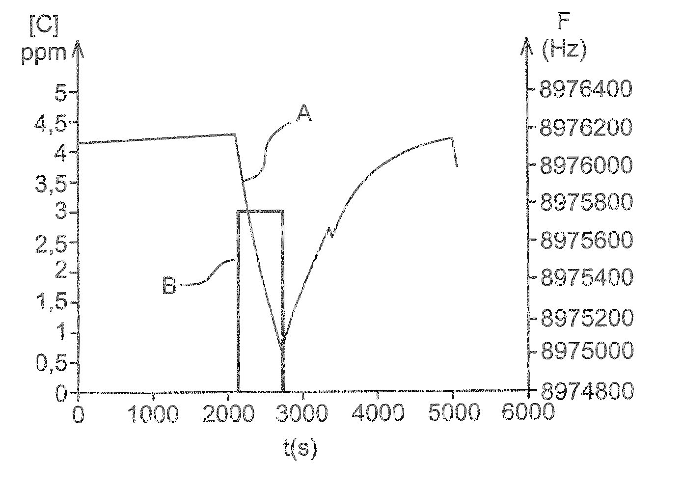
[0111]The sensor is exposed successively to:[0112]air for 2100 seconds,[0113]DNTFMB at a concentration of a 3ppm in air for 600 seconds, and[0114]air for 2310 seconds,

the air and the DNTFMB being at ambient temperature.

[0115]FIG. 1 illustrates the change in the vibration frequency of the quartz crystal over the course of these exposures.

[0116]In this figure, c...

example 3

Detection of DNTFMB by a Sensor According to the Invention

[0117]In this example, a quartz microbalance sensor was produced by covering the two faces of a quartz crystal identical to that used in Example 2, with a thin film of polymer A prepared in accordance with Example 1.

[0118]This film is deposited on each face of the quartz crystal by spraying a 10 g / l solution of polymer A in chloroform 8 times, each lasting 0.3 second.

[0119]The change in the vibration frequency of the quartz crystal due to this coating is 9.5 kHz.

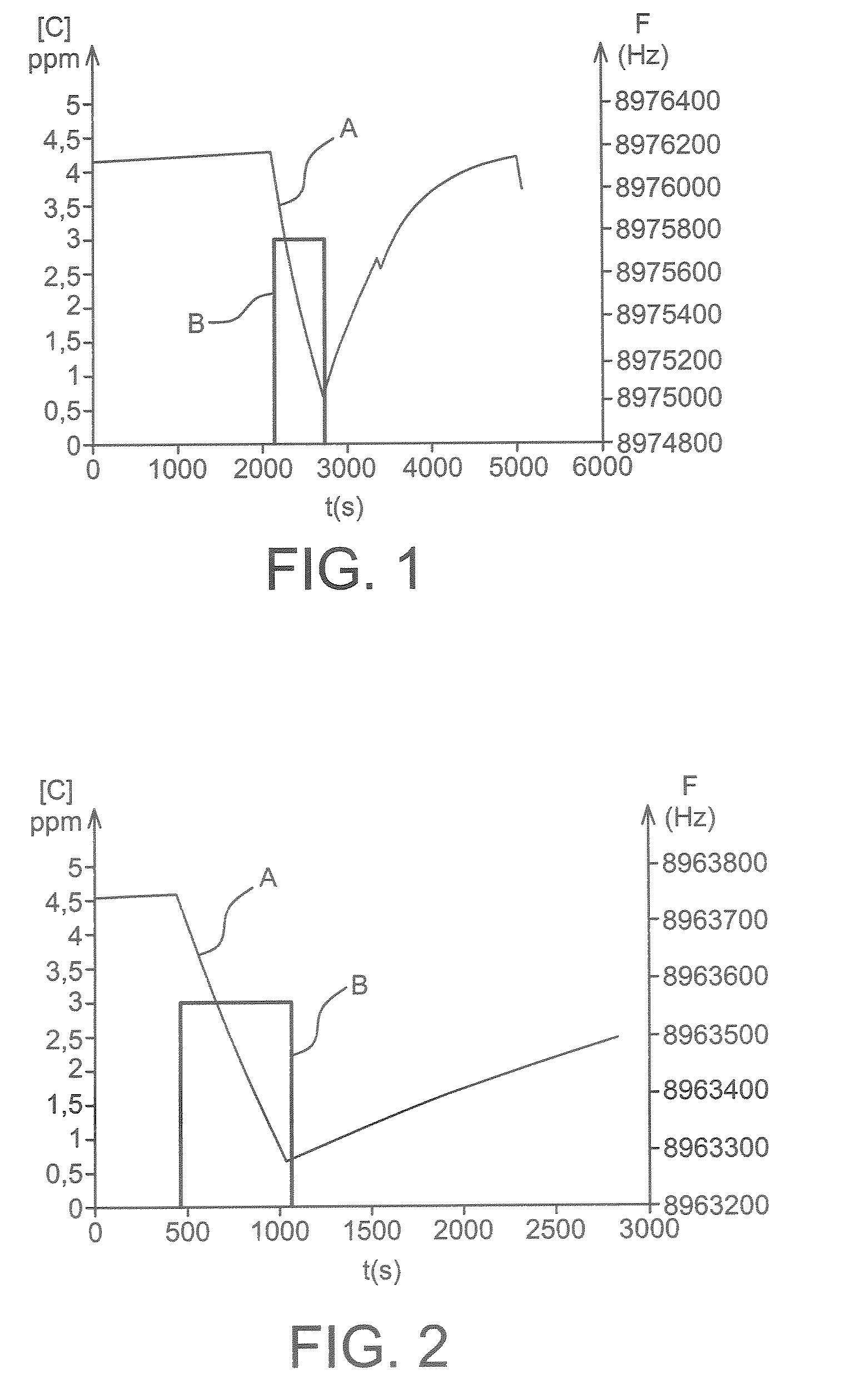
[0120]The sensor is exposed successively to:[0121]air for 460 seconds,[0122]DNTFMB at a concentration of 3 ppm in air for 600 seconds, and[0123]air for 1800 seconds,

the air and the DNTFMB being at ambient temperature.

[0124]FIG. 2 illustrates the change in the vibration frequency of the quartz crystal over the course of these exposures.

[0125]In this figure, curve A represents the values of the vibration frequency (F) of the quartz crystal, expressed in Hz (hertz), as a...


PUM

PropertyMeasurementUnit
thickaaaaaaaaaa
vibration frequencyaaaaaaaaaa

Abstract

A chemical sensor including a substrate having at least two faces, at least one of the faces being covered by a thin film that includes a sensitive material, and a means for measuring a change in a physical property of the sensitive material; and, methods of detecting the presence of a nitro compound with the chemical sensor.

Description

TECHNICAL FIELD[0001]The present invention relates to chemical sensors comprising aniline-grafted polysiloxanes as sensitive materials and to the use of these sensors for detecting or assaying nitro compounds, in particular nitroaromatic compounds such as nitrobenzene (NE), dinitrobenzene DNB), trinitrobenzene (TNB), nitrotoluene (NT), dinitrotoluene (DNT), 2,4,6-trinitrotoluene (TNT), and the like.[0002]Such sensors are useful for detecting explosives, whether for the purpose of ensuring safety in public places such as airports, for checking the legality of merchandise in circulation in a territory, for combating terrorism, for carrying out disarmament operations, for locating antipersonnel mines or even for decontaminating industrial or military sites.[0003]They are also useful for protecting the environment, in particular for checking and monitoring atmospheric pollution and the quality of the ambient air in relatively confined spaces, and also for the monitoring, for security pu...

Claims


Application Information

Patent Timeline
Patent Type & Authority Patents(United States)
IPC IPC(8): G01N33/00
CPCC08G77/045C08G77/26C08G77/388G01N27/126G01N29/036G01N33/0057Y10T436/17G01N2291/0257Y10T436/170769Y10T436/173076Y10T436/173845
Inventor POULLAIN, DIDIERPASQUINET, ERICHAIRAULT, LIONEL
Owner COMMISSARIAT A LENERGIE ATOMIQUE ET AUX ENERGIES ALTERNATIVES
Learn More