
Optical recording medium, recording and reproducing method thereof, and optical recording and reproducing apparatus

a recording medium and optical recording technology, applied in the field of optical recording medium, recording and reproducing method thereof, and optical recording and reproducing apparatus, can solve the problems of unsolved problems regarding the absorption and reflection of light in the second recording layer, and the literature does not disclose any verification results of recording signals, so as to achieve stable recording and reproducing, reduce crosstalk between recording marks, and facilitate recording signal properties

Inactive Publication Date: 2011-06-21
RICOH KK
View PDF24 Cites 0 Cited by
  • Summary
  • Abstract
  • Description
  • Claims
  • Application Information

AI Technical Summary

Benefits of technology

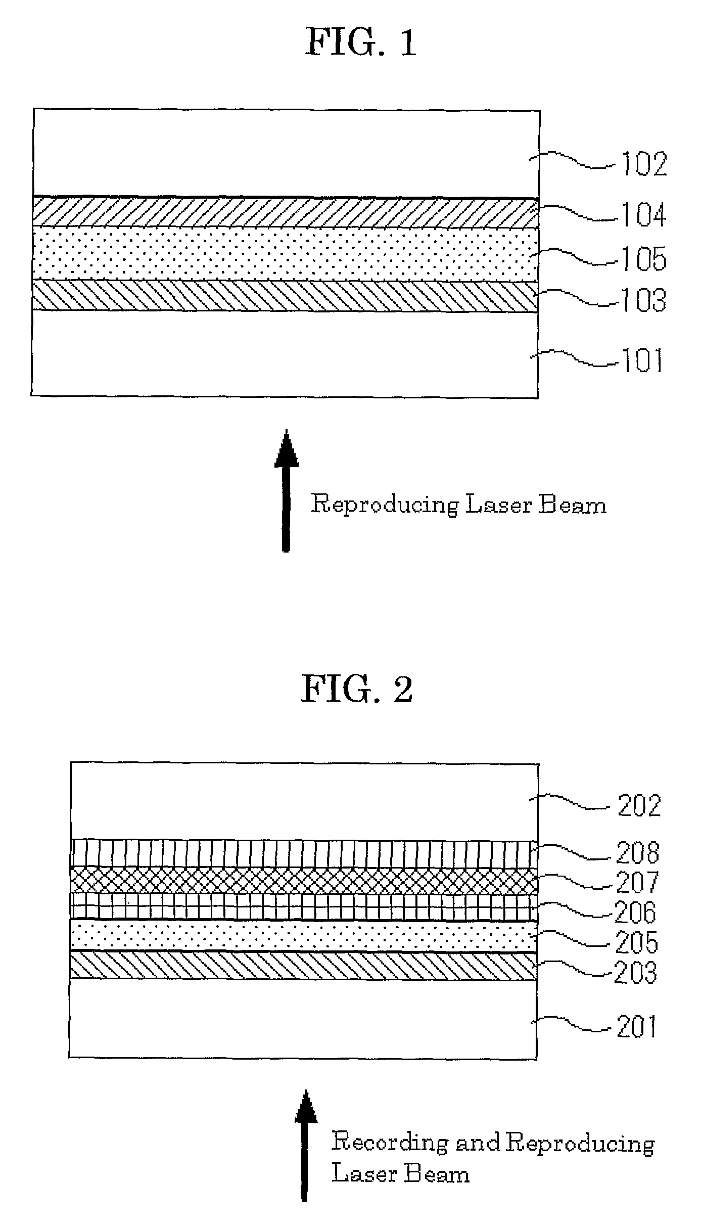
The present invention provides a high-performance single-sided double-layer optical recording medium with favorable recording signal properties in the second recording layer and reduced crosstalk between recording marks. The optical recording medium comprises a first substrate, a first information layer, an intermediate layer, a second information layer, and a second substrate. The pyrolysis temperature range of the organic dye in the second recording layer is -45°C or less. The optical recording and reproducing method involves applying a light to the surface of the first substrate and the information is recorded or reproduced on the first recording layer and the second recording layer. The optical recording and reproducing apparatus includes a light source and the optical recording medium. The technical effects of the present invention include stable recording and reproducing of information, reduced crosstalk between recording marks, and favorable recording signal properties from the second recording layer.

Problems solved by technology

A single-sided double-layer optical recording medium for recording and reproducing comprises a first recording layer and a second recording layer, and when a signal is being recorded by applying a laser that is brought to focus on the second recording layer, which is located more distant from the optical pickup, the light absorption and light reflection required for recording on the second layer are incompatible due to the attenuation of the laser in the first recording layer.
However, this literature only proposes a configuration where two existing types of substrates, one configured such that a laser is applied on the surface of the substrate for recording and the other configured such that a laser is applied from the surface of the recording layer, are laminated, and the above-noted problem regarding the absorption and reflection of light in the second recording layer remains unsolved.
Also, this patent literature does not disclose any verification results of recording signals.
In addition, there is a problem that it is difficult to form a recording mark on the second recording layer because the configuration of the recording medium is different from those of the conventional CD-R and DVD+R.
Hence, there are difficulties in achieving recording and reproducing properties such as modulation and jitter which are compliant to DVD systems.
However, these patent documents disclose only the existence and absence of a recording mark (modulation), and the proposals thereof are equivalent to the one described in Patent Literature 1, that is, a configuration where two types of substrates, one configured such that a laser is applied to the surface of the substrate for recording and the other configured such that a laser is applied to the surface of the recording layer, are laminated; and the problem regarding the recording and reproducing remains unsolved.
However, in these prior art, the performance in the formation of recording marks in the second recording layer in the case of a single-sided double-layer optical recording medium is not yet sufficient.

Method used


Image

  • Optical recording medium, recording and reproducing method thereof, and optical recording and reproducing apparatus
  • Optical recording medium, recording and reproducing method thereof, and optical recording and reproducing apparatus
  • Optical recording medium, recording and reproducing method thereof, and optical recording and reproducing apparatus

Examples


example 1

-Preparation of Optical Recording Medium-

[0143]A second substrate made of polycarbonate resin having a diameter of 120 mm and a thickness of 0.57 mm, on which a convexo-concave pattern of guide grooves having a depth of 32 nm (320 Å) and a width (at the bottom of the grooves) of 0.25 μm, wherein the pattern had a track pitch of 0.74 μm, was prepared. On the second substrate, a second reflective layer comprising AgIn (mixing ratio of Ag to In on an atomic basis is 99.5 to 0.5) having a thickness of 150 nm (1,500 Å) was formed by sputtering method with Ar as a sputtering gas.

[0144]Next, on the second reflective layer, a second recording layer having a thickness of 80 nm (800 Å) was formed by spin coating using a coating liquid prepared by dissolving a squarylium dye compound A, which is represented by the Formula (3) and having substituents shown in Table 1, in 2,2,3,3-tetrafluoropropanol.

[0145]Next, on the second recording layer, a protective layer comprising ZnS—SiC (the molar ratio...

example 7

-Preparation of Optical Recording Medium-

[0160]An optical recording medium was prepared in the same manner as Example 1, except that the thickness of the second recording layer was changed to 50 nm (500 Å) and the thickness of the protective layer, comprising ZnS—SiC, where the molar ratio of ZnS to SiC was eight to two, was changed to 180 nm (1,800 Å).

[0161]The optical recording medium was evaluated in the same manner as Example 1. It was found that the reflectivity (I14H) of 18%, the modulation (I14 / I14H) of 65% and PI Sum 8 of 20 or less after recording; signal properties satisfactory to DVD-ROM standards were obtained.

[0162]Also, the amount of crosstalk was evaluated in the same manner as Example 1. The results are shown in Table 2 and FIG. 8.

example 8

[0163]-Preparation of Optical Recording Medium-

[0164]An optical recording medium was prepared in the same manner as Example 1, except that the thickness of the second recording layer was changed to 100 nm (1,000 Å) and the thickness of the protective layer, comprising ZnS—SiC, where the molar ratio of ZnS to SiC was eight to two, was changed to 80 nm (800 Å).

[0165]The optical recording medium was evaluated in the same manner as Example 1. It was found that the reflectivity (I14H) of 19%, the modulation (I14 / I14H) of 92% and PI Sum 8 of 20 or less after recording; signal properties satisfactory to DVD-ROM standards were obtained.

[0166]Also, the amount of crosstalk was evaluated in the same manner as Example 1. The results are shown in Table 2 and FIG. 8.


PUM

PropertyMeasurementUnit
temperatureaaaaaaaaaa

Abstract

The present invention is aimed to provide a high-performance single-sided double-layer optical recording medium with reduced crosstalk between recording marks, wherein favorable recording signal properties are obtained even from the second recording layer located more distant from the substrate to which the light is applied, and reproducing method thereof, and an optical recording and reproducing apparatus. The optical recording medium possesses the following aspects: the optical recording medium comprises a first substrate, a first information layer, an intermediate layer, a second information layer and a second substrate in this order; the first information layer comprises a first recording layer; the second information layer comprises a second reflective layer, a second recording layer with an organic dye and a protective layer; and the pyrolysis temperature range, the DTA peak width of the thermal analysis on the organic dye in the second recording layer, is 45° C. or less.

Description

TECHNICAL FIELD[0001]The present invention relates to an optical recording medium (hereinafter referred to as “optical information recording medium” or “information recording medium” sometimes) which is preferably applied particularly to a write once read many DVD disc, a recording and reproducing method thereof, and an optical recording and reproducing apparatus using the optical recording medium.BACKGROUND ART[0002]In addition to an optical recording medium such as a reproduction-only Digital Versatile Disc (DVD), a recordable DVD (e.g., DVD+RW, DVD+R, DVD-R, DVD-RW and DVD-RAM) has been put to practical use.[0003]The DVD+R and DVD+RW lie at the extension of the conventional technologies for recordable compact discs (CD-R and CD-RWs), and to maintain the reproduction compatibility of the DVD+R and DVD+RW with a reproduction-only DVD, the DVD+R and DVD+RW are designed so that the recording density (e.g., track pitch and signal mark length) and the thickness of substrate are compati...

Claims


Application Information

Patent Timeline
Patent Type & Authority Patents(United States)
IPC IPC(8): B32B3/02G11B7/24038G11B7/246G11B7/2463G11B7/2467G11B7/247G11B7/2472G11B7/249G11B7/253G11B7/2534G11B7/257G11B7/2578G11B7/258G11B7/2585G11B7/259G11B7/2595
CPCG11B7/24038G11B7/246G11B7/249Y10T428/21G11B7/2463G11B7/2467G11B7/2472G11B7/248G11B7/2534G11B7/2578G11B7/2585G11B7/259G11B7/2595G11B2007/25706G11B2007/25708G11B2007/2571G11B2007/25711G11B2007/25715G11B2007/25716G11B2007/25718G11B7/245
Inventor YASHIRO, TOHRU
Owner RICOH KK
Learn More