
Method and apparatus for enhanced terahertz radiation from high stacking fault density

a stacking fault density and terahertz radiation technology, applied in the field of radiation emitting crystals, can solve the problems of limited thz pulse energy, high restrictive semiconductor material, and limited external bias voltage, so as to achieve enhanced terahertz radiation levels

Active Publication Date: 2011-04-05
UNITED STATES OF AMERICA THE AS REPRESENTED BY THE SEC OF THE ARMY
View PDF1 Cites 8 Cited by
  • Summary
  • Abstract
  • Description
  • Claims
  • Application Information

AI Technical Summary

Benefits of technology

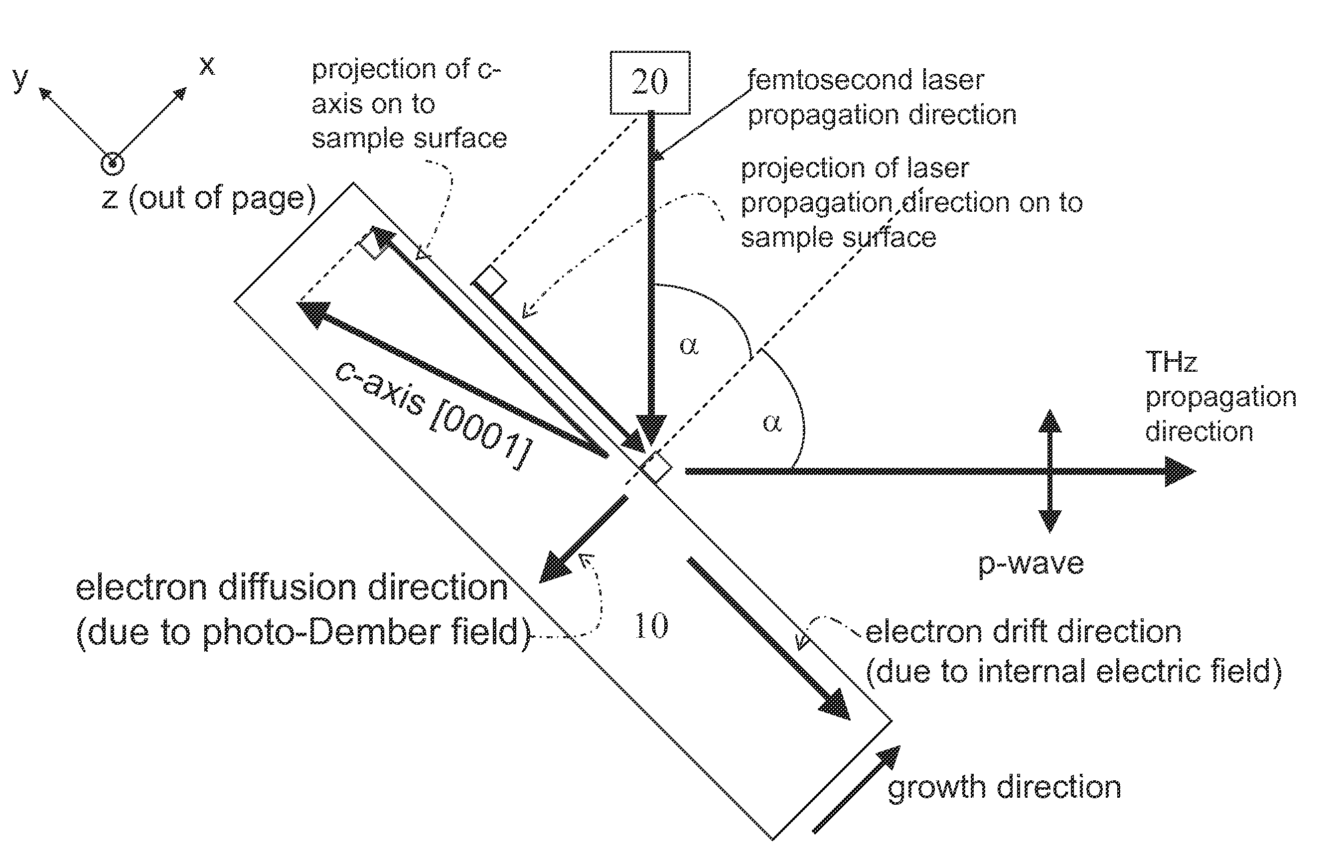
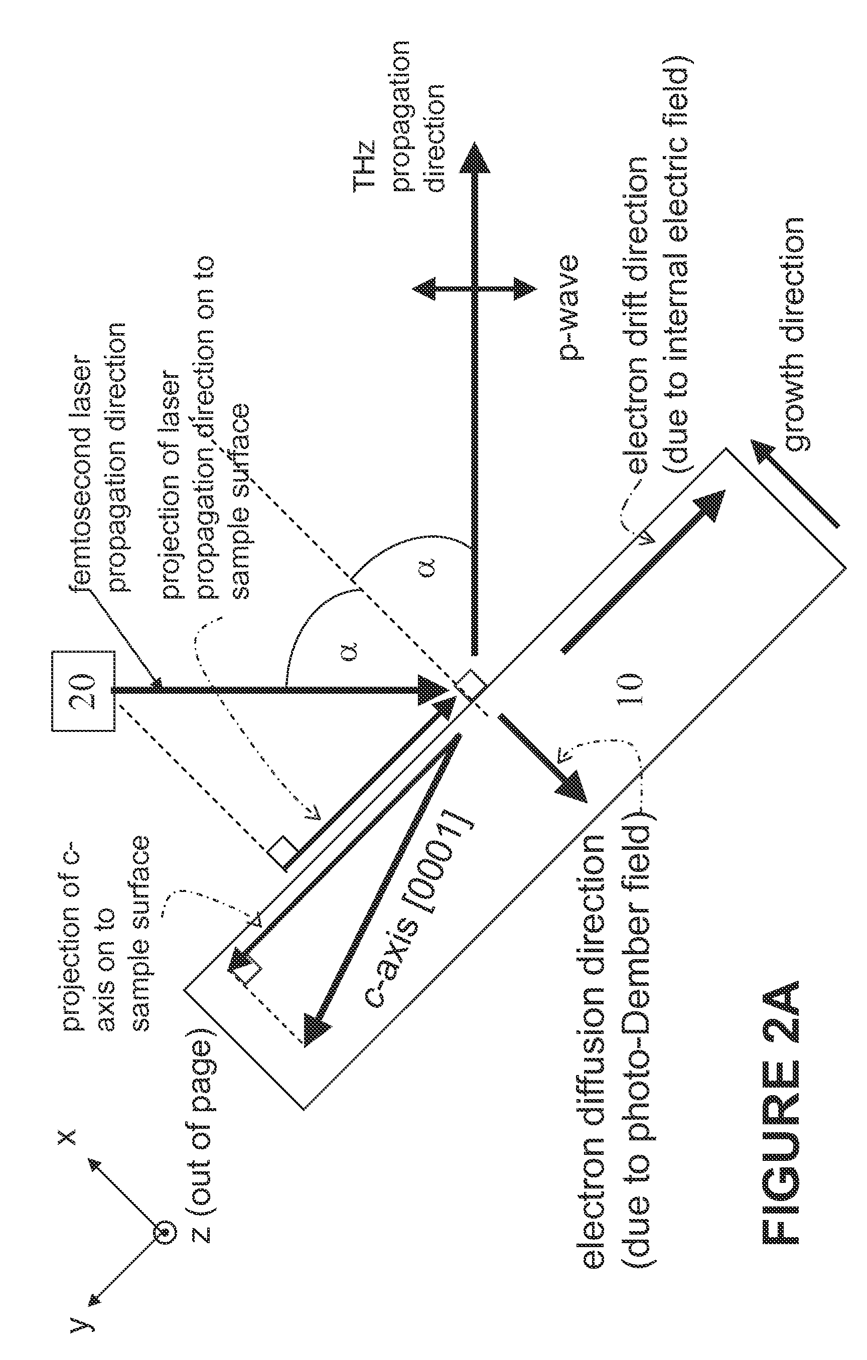
[0012]The present invention results in spectrally broadened emission and greater efficiency of emitting devices. The p-polarized (s-polarized) THz radiation measured from the high stacking fault density samples reaches its maximum and minimum when the c-axis is parallel or antiparallel with the p-polarization (s-polarization) detection direction, respectively.
[0014]In order to attain the objectives described above, according to the present invention, there is provided an apparatus and methodology whereby enhanced levels of terahertz radiation are obtainable.

Problems solved by technology

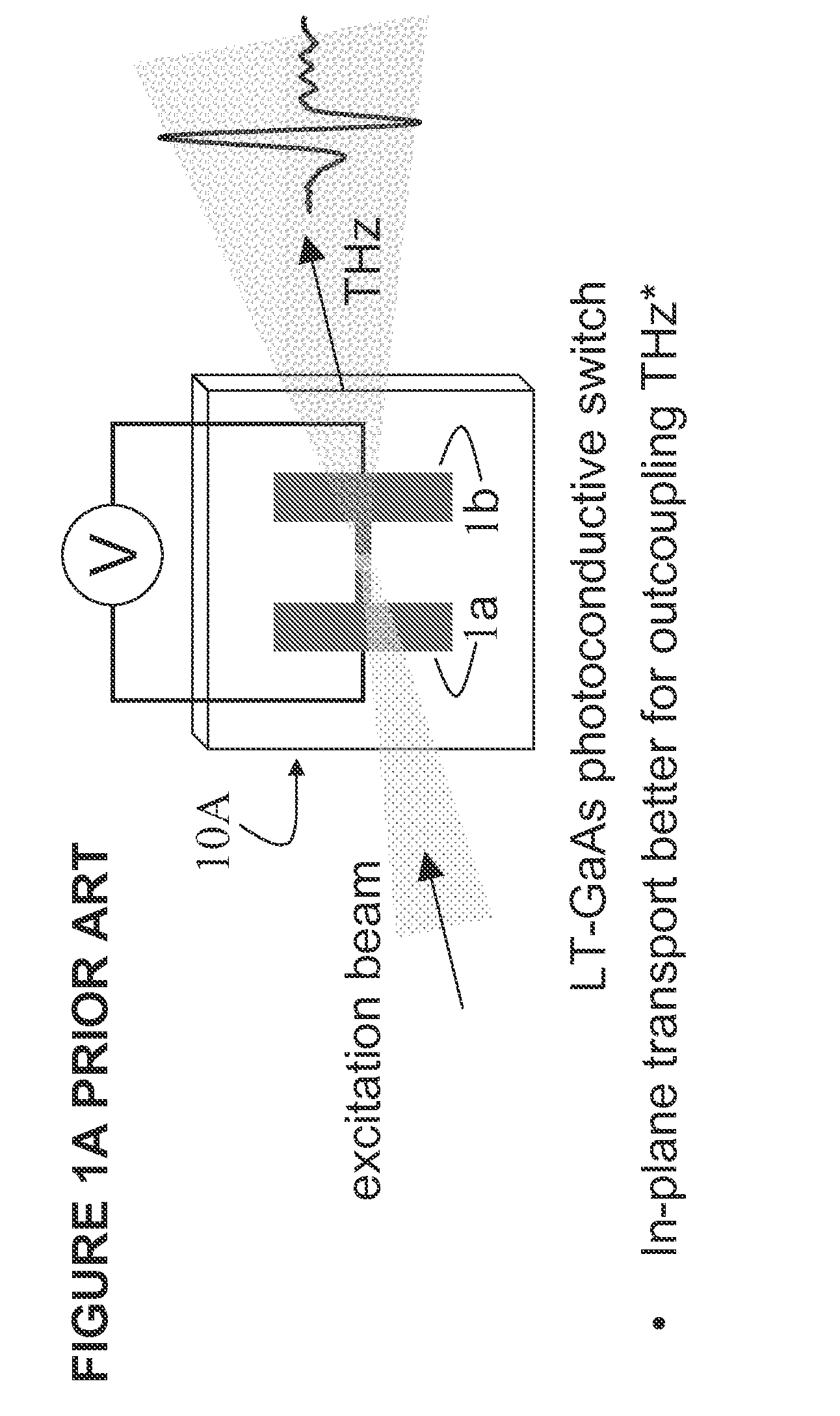
The semiconductor material is highly restrictive, such that virtually no current flows without illumination.
One disadvantage of this approach is that metal electrodes with kV voltages across them must be used to create THz radiation.
Another disadvantage is that the external bias voltage, and therefore the THz pulse energy, is limited by dielectric breakdown in air to less than 300 kV / cm in theory, but in practice 100 kV / cm is rarely exceeded.
Although the geometry of the biased photoconductive antennas is more favorable for coupling out the THz radiation than that for other semiconductor-based THz sources employing transport normal to the surface, these photoconductive switches require electrode processing and an external bias voltage, which is limited by the dielectric strength of air, to establish an in-plane electric field.

Method used


Image

  • Method and apparatus for enhanced terahertz radiation from high stacking fault density
  • Method and apparatus for enhanced terahertz radiation from high stacking fault density
  • Method and apparatus for enhanced terahertz radiation from high stacking fault density

Examples


Embodiment Construction

[0042]The present invention now will be described more fully hereinafter with reference to the accompanying drawings, in which embodiments of the invention are shown. However, this invention should not be construed as limited to the embodiments set forth herein. Rather, these embodiments are provided so that this disclosure will be thorough and complete, and will fully convey the scope of the invention to those skilled in the art. In the drawings, the thickness of layers and regions may be exaggerated for clarity. Like numbers refer to like elements throughout. As used herein the term “and / or” includes any and all combinations of one or more of the associated listed items.

[0043]The terminology used herein is for the purpose of describing particular embodiments only and is not intended to limit the full scope of the invention. As used herein, the singular forms “a”, “an” and “the” are intended to include the plural forms as well, unless the context clearly indicates otherwise. It wil...


PUM


Abstract

A method and device for generating terahertz radiation comprising a polar crystal material layer operative to emit terahertz radiation; the polar crystal material layer comprising a plurality of stacking faults; the stacking faults lying substantially perpendicular to the polar axis and forming boundaries at which the internal electric polarization terminates leading to charges accumulating at the boundaries, and creation of internal electric fields oriented along the polar axis; a pulsed radiation source for creating photogenerated carriers in the polar crystal material; whereby the photogenerated carriers accelerate in the internal electric fields associated with the termination of the internal electric polarization by the stacking faults to thereby generate terahertz radiation.

Description

CROSS-REFERENCE TO RELATED APPLICATIONS[0001]This application claims priority of U.S. Provisional Patent Application Ser. No. 61 / 050,890 filed May 6, 2008, which is incorporated herein by reference.GOVERNMENT INTEREST[0002]The invention described herein may be manufactured, used, and / or licensed by or for the United States Government.FIELD OF THE INVENTION[0003]This invention relates generally to radiation emitting crystals, and more particularly to crystal structures which provide a source of terahertz radiation.BACKGROUND OF THE INVENTION[0004]Electromagnetic waves sent at terahertz frequencies, known as terahertz radiation, terahertz waves (THz) rays, occur in the region of the electromagnetic spectrum between 300 gigahertz (3×10¹¹ Hz) and 3 terahertz (3×10¹² Hz), and correspond to the wavelength range of between 1 millimeter (high-frequency edge of the microwave band) and 100 micrometer (long-wavelength edge of far-infrared light).[0005]THz-rays, which are shorter than microwave...

Claims


Application Information

Patent Timeline
Patent Type & Authority Patents(United States)
IPC IPC(8): H01L33/04H01L33/28H01L33/32
CPCG02F2/004H01S1/02G02F2203/13G02F2002/006G02F2/006
Inventor METCALFE, GRACE D.WRABACK, MICHAELSHEN, PAUL
Owner UNITED STATES OF AMERICA THE AS REPRESENTED BY THE SEC OF THE ARMY
Learn More