
Eccentric screw pump equipped with erosion-resistant rotor

a technology of rotor and eccentric screw, which is applied in the direction of rotary or oscillating piston engines, engine lubrication, rotary piston engines, etc., can solve the problems of insufficient corrosion resistance of rotors, insufficient wear strength of steel materials, and insufficient corrosion resistance for some applications, so as to achieve greater erosion resistance and better wear resistance

Inactive Publication Date: 2011-03-22
VILGELM KAKHELLE GMBKH
View PDF10 Cites 2 Cited by
  • Summary
  • Abstract
  • Description
  • Claims
  • Application Information

AI Technical Summary

Benefits of technology

[0006]In view of the foregoing, a general object of the invention is to provide an eccentric screw pump or an eccentric screw motor in which the rotor is characterized by better erosion resistance. Another general object of the invention is to provide a method for producing a rotor having greater erosion resistance.
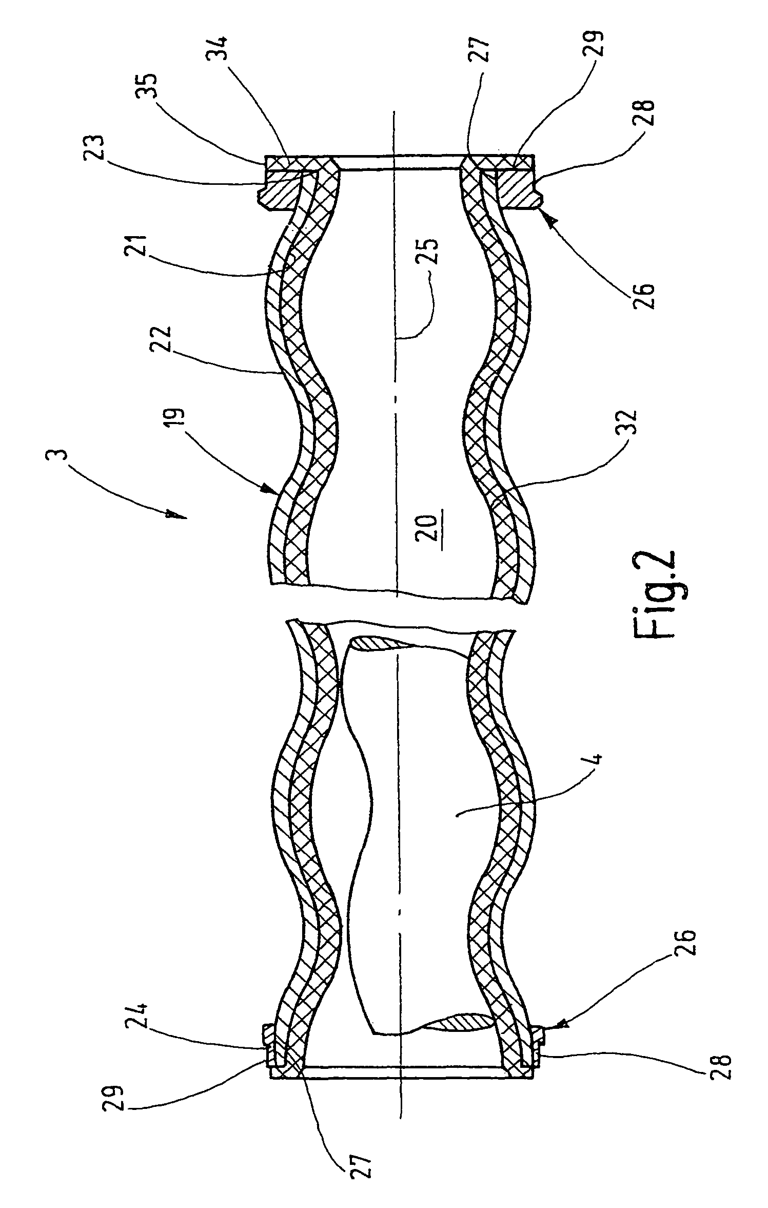
[0007]The rotor in the eccentric screw pump or screw motor according to the invention is designed like a sandwich. The rotor consists of a radially inner layer and a radially outer layer with the radially outer layer being especially adapted to provide higher erosion resistance. In particular, the radially outer layer can be more abrasion-resistant or more corrosion-resistant or both than the radially inner layer.
[0009]The rotor can have a very homogeneous structure if the inner layer consists of a seamless tube. Such an arrangement helps avoid heterogeneities, which otherwise occur during welding. Such heterogeneities could continue outward as shape defects. However, it is also possible to use a wound tube as the inner tube in the present invention. Such a tube is preferably laser-welded at the helical butt joint. The coil should run opposite the coil of the outer layer.
[0011]Stainless steels V2A, V4A steel or other abrasion-resistant steels can be used as the outer material. Since these materials have a very much higher specific weight than normal steel, the two-layer design also results in a weight saving as compared to a rotor made only of stainless steel. This can play a role in rotors with a length of up to 6 meters.
[0012]The strength of the rotor can be improved if it includes a core element. The rotor can be molded around the core element so that a good connection with the core element is produced. The core element prevents uncoiling of the rotor under load at great lengths. In addition, additional torque can be introduced over the length of the rotor by means of the core element. The substantially rotationally symmetric and non-helical core is better suited for this purpose. The core element can be tubular or solid. In addition, the intermediate space between the tube or shell of the rotor and the core element can be either left open or filled with a mass.
[0015]The outer metal layer in the simplest case consists of a metal band wrapped around the tube. To increase the tension the metal band can be heated immediately ahead of the contact site before winding. Subsequent cooling ensures shrinkage that holds the metal band particularly tightly on the surface of the tube. The butt joint between the adjacent windings can be welded in order to prevent penetration of particles.

Problems solved by technology

Uncoiling of the rotor could lead to a pitch error between the stator and rotor that would result in leaks.
This prior art rotor is made of a steel material that does not have sufficient wear strength for many applications, and also does not have sufficient corrosion-resistance for some applications.
In other words, the rotor does not have sufficient erosion resistance.

Method used


Image

  • Eccentric screw pump equipped with erosion-resistant rotor
  • Eccentric screw pump equipped with erosion-resistant rotor
  • Eccentric screw pump equipped with erosion-resistant rotor

Examples


Embodiment Construction

[0023]A schematized, oblique view an eccentric screw pump 1 according to the invention is shown in FIG. 1. The eccentric screw pump 1 includes a pump head 2, a stator 3 in which a rotor 4 rotates, as well as a connection head 5. The pump head 2 has a substantially cylindrical housing 6, which includes a closure cover 7 on one end with a closure cover 7. A drive shaft 8 is guided outward in sealed fashion through the closure cover 7. A connector 9 discharges radially into housing 6. The housing 6 ends in a fastening flange 11. As is common in eccentric screw pumps, the coupling piece for torque-proof coupling the drive shaft 8 (which is connected to a drive motor) to the rotor 4 is situated inside the housing 6.

[0024]The end of the housing 6 that is remote from the cover 7 is provided with a tightening flange 12 that has a diameter greater than the diameter of the substantially cylindrical housing 6. The tightening flange 12 has a stepped hole 13 that is aligned with the internal spa...


PUM

PropertyMeasurementUnit
Thicknessaaaaaaaaaa
Massaaaaaaaaaa
Electrical resistanceaaaaaaaaaa

Abstract

An eccentric screw pump or an eccentric screw motor has a rotor formed from at least a tubular jacket with at least two layers. The outer layer of the jacket consists of a material that is abrasion-resistant and / or corrosion-resistant.

Description

BACKGROUND OF THE INVENTION[0001]A rotor for an eccentric screw pump or eccentric screw motor produced by cold deformation is disclosed in DE 198 52 380 A1. The pump or motor of this reference has a stator with a continuous helical opening over which the rotor rolls during displacement operation. The stator comprises a cylindrical tube provided with an elastomeric cladding. The elastomeric cladding defines the wall of the passage opening and acts as a seal relative to the stator.[0002]The stator includes a core element and a shell formed around the core element. Beginning with a cylindrical tube, the shell is deformed into a helical configuration. The originally cylindrically shaped tube acquires not only the helical configuration, which is required for the rotor, but this deformation also firmly connects the tube to the core element. In the final state, the thread valleys of the shell of the stator form a tight firm friction fit with the core element. To improve the driving effect ...

Claims


Application Information

Patent Timeline
IPC IPC(8): F01C1/10F01C5/00F03C2/00F04C2/107
CPCF04C2/1071F04C2230/231Y10T29/49865Y10T29/49242F04C2240/20
Inventor KACHELE, BRUNO
Owner VILGELM KAKHELLE GMBKH
Learn More