
Battery

a battery and battery technology, applied in the field of batteries, can solve the problems of insufficient cycle characteristics and small cracking of lithium alloy, and achieve the effects of preventing the reaction between anode and electrolyte, high capacity, and improving charge and discharge efficiency

Active Publication Date: 2011-03-15
SONY CORP +1
View PDF18 Cites 5 Cited by
  • Summary
  • Abstract
  • Description
  • Claims
  • Application Information

AI Technical Summary

Benefits of technology

The present invention provides a battery with a high capacity and improved battery characteristics, such as cycle characteristics. The battery includes a cathode, an anode, and an electrolyte. The anode includes at least one anode active material, such as simple substances, alloys, and compounds of metal elements and simple substances, and the electrolyte includes a light metallic salt having M-X bond where M represents a transition metal element or a 3B Group element, a 4B Group element, or a 5B Group element in the short-period periodic table; and X represents oxygen, sulfur, or the like. The electrolyte can also include a light metallic salt having B—O bond or P—O bond, which can provide higher efficiency. Additionally, other light metallic salt can be included to lower internal resistance and improve battery characteristics.

Problems solved by technology

However, there has been a problem that the lithium alloy is cracked into small pieces due to its intense expansion and shrinkage after repeating charge and discharge.
Therefore, there has been a problem that when the lithium alloy is used for the anode, electronic conduction is lowered due to miniaturization from breaking of particles or reduced contact area between particles in the anode, and decomposition reaction of a solvent is improved due to increase of surface area, leading to insufficient cycle characteristics.

Method used


Image

  • Battery
  • Battery
  • Battery

Examples


examples 1-1 to 1-18

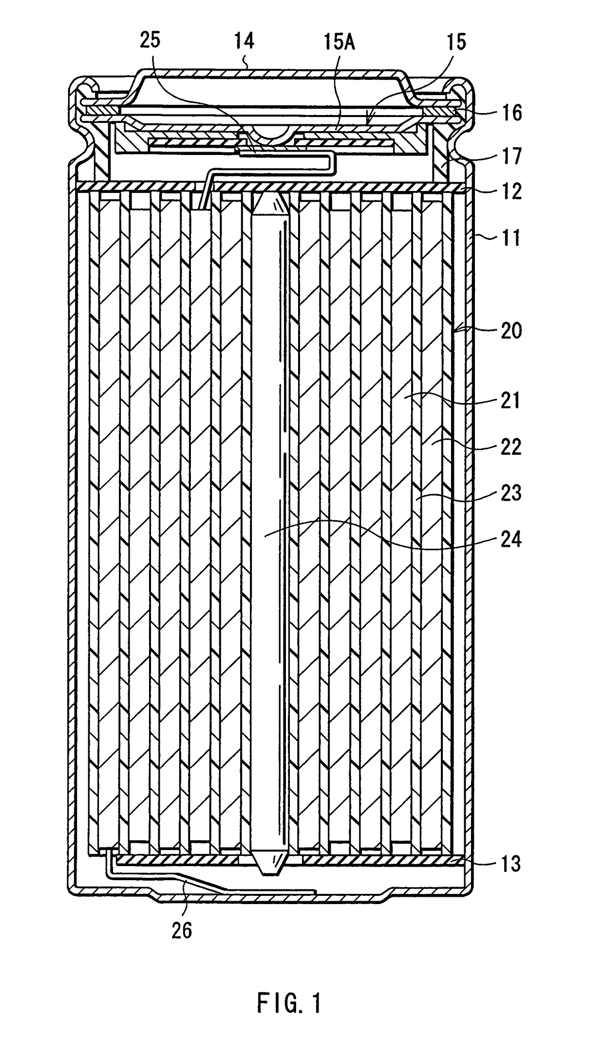
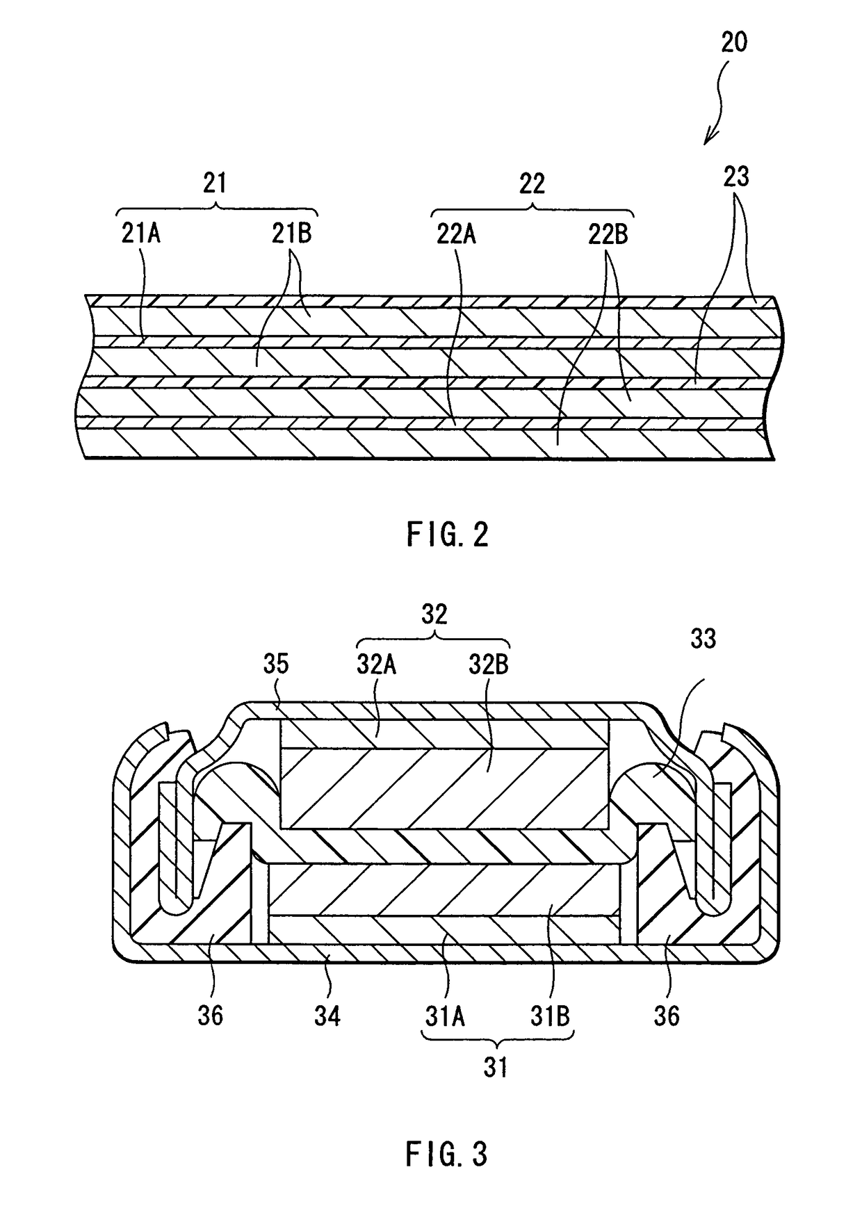
[0090]Cylindrical secondary batteries shown in FIGS. 1 and 2 were fabricated as follows. First, lithium carbonate (Li2CO3) and cobalt carbonate (CoCO3) were mixed at a ratio (molar ratio) of Li2CO3:CoCO3=0.5:1. The mixture was fired for 5 hours at 900° C. in the air to obtain lithium cobalt complex oxide (LiCoO2) as a cathode active material. Next, 91 parts by mass of lithium cobalt complex oxide, 6 parts by mass of graphite as a conductive agent, and 3 parts by mass of polyvinylidene fluoride as a binder were mixed to prepare a cathode mixture. Subsequently, this cathode mixture was dispersed in N-methyl-2-pyrolidone of a solvent to obtain a cathode mixture slurry. This cathode mixture slurry was uniformly applied on both sides of the cathode current collector 21A made of a strip shaped aluminum foil having a thickness of 20 μm, dried, and compression-molded to form the cathode active material layer 21B. Then, the resultant was cut in the shape of a strip to form the strip shaped c...

example 2-1 and 2-2

[0102]Secondary batteries were fabricated in a manner similar to in Examples 1-1 to 1-18, except that tin was used as the anode active material, the anode active material layer 22B made of tin having a thickness of 2 μm was formed on the anode current collector 22A made of an electrolytic copper foil having a thickness of 25 μm by electron beam deposition method, and the resultant was provided with heat treatment for 12 hours at 200° C. to form the anode 22. In this regard, types and contents of the light metallic salt were changed as shown in Table 2. When the obtained anode 22 was analyzed by XPS (X-ray Photoelectron Spectroscopy), AES (Auger Electron Spectroscopy), and X-ray diffraction method, it was confirmed that the anode active material layer 22B was alloyed with the anode current collector 22A at least on part of the interface with the anode current collector 22A.

[0103]

TABLE 2CapacityAnodeElectrolyte saltInitialInternalretentionFormingContentcapacityresistanceratioMaterialm...

examples 3-1 to 3-39

[0108]Silicon of an anode active material was deposited to form the anode active material layer, and coin type secondary batteries shown in FIG. 3 were fabricated. In this secondary battery, a discoid cathode 31 and a discoid anode 32 are layered with a separator 33 in between, and the lamination is housed between an exterior can 34 and an exterior cup 35.

[0109]First, lithium cobalt complex oxide of a cathode active material having an average particle diameter of 5 μm, carbon black of a conductive agent, and polyvinylidene fluoride of a binder were mixed at a mass ratio of 92:3:5 to prepare a cathode mixture. Next, this cathode mixture was dispersed in N-methyl-2-pyrolidone of a solvent to obtain a cathode mixture slurry. This cathode mixture slurry was applied on a cathode current collector 31A made of a strip shaped aluminum foil having a thickness of 20 μm, dried, and compression-molded to form a cathode active material layer 31B. The cathode 31 was thereby fabricated.

[0110]An el...


PUM

PropertyMeasurementUnit
roughnessaaaaaaaaaa
thicknessaaaaaaaaaa
temperatureaaaaaaaaaa

Abstract

A battery is provided which has a high capacity and can improve battery characteristics, such as cycle characteristics. The battery includes a spirally wound electrode body, wherein a cathode and an anode are wound with a separator in between. The anode includes, for example, simple substances, alloys, compounds of metal elements or metalloid elements capable of forming an alloy with Li, the like and combinations thereof. An electrolytic solution wherein an electrolyte salt is dissolved in a solvent is impregnated in the separator. For the electrolyte salt, a light metallic salt having B—O bond or P—O bond, such as difluoro[oxalato-O,O′]lithium borate and tetra fluoro[oxalato-O,O′]lithium phosphate, can be used. By forming a stable coating, decomposition reaction of the solvent can be inhibited, and reaction between the anode and the solvent can be prevented.

Description

CROSS REFERENCES TO RELATED APPLICATIONS[0001]This application claims priority to Japanese Patent Application Nos. P2003-166861 filed on Jun. 11, 2003, and P2003-414622 filed on Dec. 12, 2003, the disclosures of which are incorporated by reference herein.BACKGROUND OF THE INVENTION[0002]The present invention generally relates to a battery including a cathode, an anode, and an electrolyte.[0003]In recent years, downsizing and weight saving of portable electronic devices typified by a mobile phone, a PDA (Personal Digital Assistant), and a laptop computer have been energetically made. As part of this situation, improvement of an energy density of a battery, particularly a secondary battery as a driving power source for these electronic devices has been strongly aspired.[0004]As a secondary battery coverable of obtaining a high energy density, a battery, wherein a lithium alloy is used for an anode has been developed (for example, refer to Japanese Unexamined Patent Application Publica...

Claims


Application Information

Patent Timeline
Patent Type & Authority Patents(United States)
IPC IPC(8): H01M4/58H01M6/04H01M4/64H01M4/134H01M4/1395H01M4/36H01M4/38H01M4/485H01M4/587H01M4/62H01M10/05H01M10/052H01M10/0525H01M10/0562H01M10/0565H01M10/0567H01M10/0568
CPCH01M10/052H01M10/054H01M10/0568H01M4/134H01M10/0565H01M2300/0025Y02E60/122Y02E60/10H01M10/05H01M10/058
Inventor ADACHI, MOMOEFUJITA, SHIGERUAOKI, MASAHIROAKASHI, HIROYUKINARUSE, YOSHIAKI
Owner SONY CORP
Learn More