
Method of making a non-compliant balloon for a catheter

a balloon catheter and non-compliant technology, applied in the field of balloon catheters, can solve the problems of catheter withdrawal, catheter difficulty in advancing through the patient's narrow vasculature, and trauma to the vessel wall, and achieve the effect of improving performance and improving control over the dilatation

Inactive Publication Date: 2011-02-22
ABBOTT CARDIOVASCULAR
View PDF66 Cites 21 Cited by
  • Summary
  • Abstract
  • Description
  • Claims
  • Application Information

AI Technical Summary

Benefits of technology

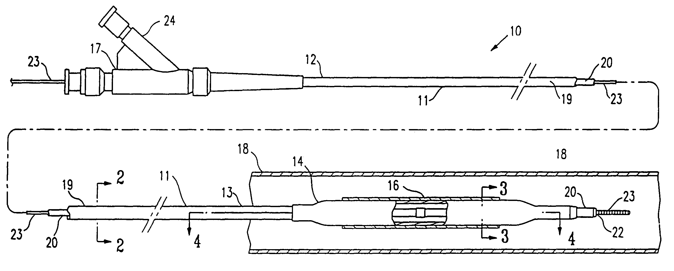
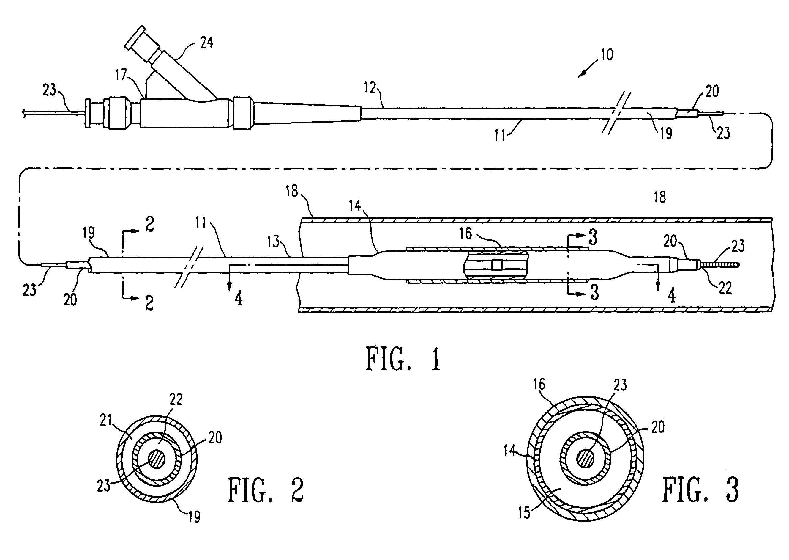
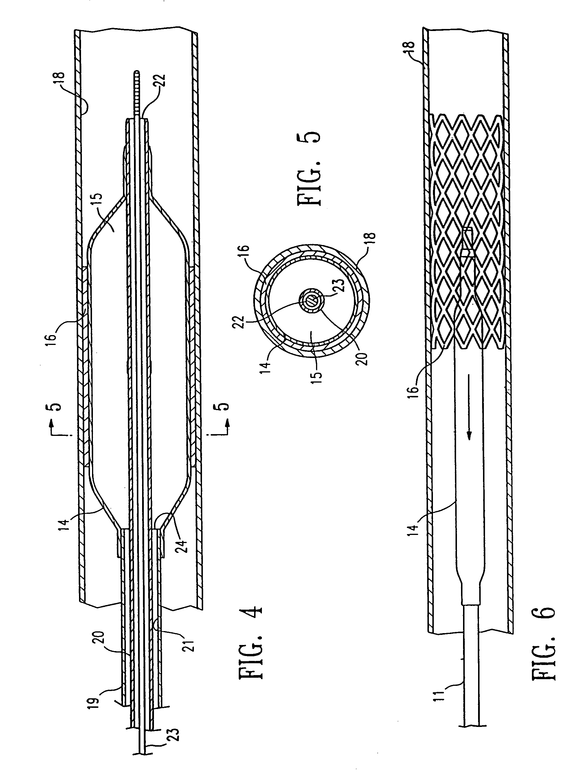
[0010]When the stent delivery balloon of the invention is pressurized, the balloon expands radially in a uniform manner to a working diameter. Because the balloon expands uniformly without unwrapping wings, it will uniformly expand a stent mounted on the balloon. The uninflated balloon does not require folding into a low profile configuration for insertion into the patient or the use of elastomeric sleeves used with conventional stent deploying balloons made from relatively non-compliant material. Similarly, the balloon of the invention should have a substantial elastic recoil so that it deflates into a smaller diameter with little or no wings. The undesirable flat or pancake shape wings which form when conventional stent deploying balloons are deflated are thus avoided. Additionally, minimal axial growth of the balloons during inflation provides improved control over the placement of the implanted stent in the body lumen. The compliant balloon results in improved abrasion and puncture resistance relative to the conventional non-compliant stent deploying balloons at least in part because there is little or no movement between the balloon and stent when the balloon expands radially. Moreover, due to the compliant nature of the balloon, there is a more highly efficient transfer of force to the stent than with the high pressure non-compliant conventional balloons which expend much expansive force to overcome rigidity (non-compliance) and to size the stent.
[0014]The semi-compliant block copolymer balloon of the invention provides improved performance due to the strength and softness of the balloon, with controlled expansion at relatively high pressures, and without the stiffness or poor refold characteristics of noncompliant balloons. Moreover, the low axial growth of the balloon during inflation provides improved control over the dilatation of a stenosis or implantation of a stent.

Problems solved by technology

Substantial, uncontrolled expansion of the balloon against the vessel wall can cause trauma to the vessel wall.
Because the non-compliant material has a limited ability to expand, the uninflated balloon must be made sufficiently large that, when inflated, the balloon has sufficient working diameter to compress the stenosis and open the patient's passageway.
However, a large profilenon-compliant balloon can make the catheter difficult to advance through the patient's narrow vasculature because, in a uninflated condition, such balloons form flat or pancake shape wings which extend radially outward.
These wings on the deflated balloon are undesirable because they result in an increased balloon profile which can complicate withdrawing the catheter after stent deployment.
Although stents have been used effectively for some time, the effectiveness of a stent can be diminished if it is not properly implanted within the vessel.
However, such sleeves may fail to completely prevent the nonuniform expansion of the stent, they increase the deflated profile upon insertion into the patient, and they complicate the assembly of the stent onto the balloon.
Additionally, the final location of the implanted stent in the body lumen may be beyond the physician's control where longitudinal growth of the stent deploying balloon causes the stent's position on the balloon to shift during deployment.
Thus, balloons which have a large amount of longitudinal growth during inflation provide inadequate control over the location of the implanted stent.

Method used


Image

  • Method of making a non-compliant balloon for a catheter
  • Method of making a non-compliant balloon for a catheter
  • Method of making a non-compliant balloon for a catheter

Examples


example 1

[0037]TECOTHANE 1065D was used to prepare balloon tubing having a mean ID of about 0.0195 inch (0.5 mm) and a mean OD of about 0.0355 inch (0.9 mm), and the balloon tubing was used to prepared balloons having an OD of about 2.5 mm. The mean balloon OD was about 0.110 inch (2.8 mm), and mean dual wall thickness was about 0.0015 inch (0.038 mm). The mean rupture pressure was about 238 psi, and the mean hoop strength was about 18,000 psi. Radial (OD) and axial (length) compliance measurements were made on the unrestrained balloons. The term unrestrained refers to a balloon with one end attached to an inflation medium source and the other end clamped shut, as opposed to a balloon with proximal and distal ends secured to a catheter shaft. The balloons have a substantially uniform radial expansion, as illustrated in Table 1, which lists the average balloon OD for the unruptured balloons, at a given inflation pressure, for five balloons tested. The balloons also have minimal axial growth d...

example 2

[0046]Balloons having a nominal OD of about 3.0 mm, and a length of about 20 mm were prepared using the method of the invention. PELLETHANE 75D was used to prepare balloon tubing having an ID of about 0.015 inch (0.381 mm) to about 0.0195 inch (0.495 mm), and an OD of about 0.031 inch (0.787 mm) to about 0.036 inch (914 mm). The balloon tubing was heated and stabilized at 40° C. for 16 to 24 hours prior to being blown into balloons. The balloon tubing was then placed in a balloon mold and stretched axially, and the mold was heated to a wall temperature of about 100-120° C. To expand the balloon tubing, the tubing was heated to a blow temperature of about 100° C., by displacing a heat nozzle at about 1 mm / sec to about 5 mm / sec from one end of the mold to the opposite end, while pressurizing the tubing at an expansion pressure of about 220 psi to about 270 psi. The expanded tubing was then heat treated within the mold and at the expansion pressure, at a heat treating temperature equal...

example 3

[0047]PELLETHANE 75D was used to prepare balloon tubing having an ID of about 0.017 inch (0.43 mm) and an OD of about 0.032 inch (0.8 mm), and the balloon tubing was used to prepared a balloon having a nominal OD of about 3.0 mm using the method of the invention as outlined above, in which the expanded tubing was heat treated at a temperature greater than the blowing temperature. The rupture pressure was about 300 psi to about 350 psi. Radial (OD) and axial (length) compliance measurements were made on the unrestrained balloon. The term “unrestrained” refers to a balloon with one end attached to an inflation medium source and the other end clamped shut, as opposed to a balloon with proximal and distal ends secured to a catheter shaft. The balloon has a semi-compliant radial expansion, as illustrated in Table 3, which lists the balloon OD for the unruptured balloon, at a given inflation pressure. The compliance of the balloon over a pressure range of about 30 psi to about 300 , or to...


PUM

PropertyMeasurementUnit
Temperatureaaaaaaaaaa
Timeaaaaaaaaaa

Abstract

An intravascular catheter system for properly implanting a stent in a body lumen generally comprising a catheter having an elongated shaft with an inflatable balloon formed of compliant material and a stent mounted on the working length of the balloon. The balloon material is compliant within the working range of the balloon to provide substantial radial expansion. The wingless radially expansive balloon expands in a uniform manner, thereby producing uniform expansion and implantation of the stent. Another embodiment is directed to a balloon catheter, having a semi-compliant balloon or a noncompliant balloon formed at least in part of a block copolymer.

Description

[0001]This application is a divisional of application Ser. No. 09 / 733,120 filed Dec. 8, 2000 now abandoned which is continuation-in-part application of Ser. No. 09 / 295,694, filed Apr. 21, 1999, now U.S. Pat. No. 6,488,688 which is a continuation-in-part application of Ser. No. 09 / 063,969, filed Apr. 21, 1998, now U.S. Pat. No. 6,287314.BACKGROUND OF THE INVENTION[0002]The invention relates to the field of intravascular catheters, and more particularly to a balloon catheter.[0003]In percutaneous transluminal coronary angioplasty (PTCA) procedures a guiding catheter is advanced until the distal tip of the guiding catheter is seated in the ostium of a desired coronary artery. A guidewire, positioned within an inner lumen of an dilatation catheter, is first advanced out of the distal end of the guiding catheter into the patient's coronary artery until the distal end of the guidewire crosses a lesion to be dilated. Then the dilatation catheter, having an inflatable balloon on the distal ...

Claims


Application Information

Patent Timeline
IPC IPC(8): B29C47/00B29C49/04B29C71/02A61F2/06A61F2/84A61L29/04A61M25/00B29C48/00B29C48/09B29C48/21
CPCA61F2/958A61L29/049A61M25/1027A61M25/1029A61M29/02B29C47/0023B29C47/065B29C55/24A61M25/104B29C47/00B29K2075/00B29L2022/022B29L2031/7542B29C48/00B29C48/09B29C48/21
Inventor LIM, FLORENCIABEI, NIANJIONGLONG, CHI LE
Owner ABBOTT CARDIOVASCULAR
Learn More