Common-path interferometer rendering amplitude and phase of scattered light

a common-path interferometer and scattering light technology, applied in the field of interferometers for nanoparticle detection, can solve the problem that the shift interferometer based on point diffraction does not enable control over the relative intensity of the reference beam, and achieve the effect of improving the ability to distinguish among sample materials and signal-to-noise levels

Inactive Publication Date: 2011-01-25
UNIVERSITY OF ROCHESTER
View PDF7 Cites 10 Cited by
  • Summary
  • Abstract
  • Description
  • Claims
  • Application Information

AI Technical Summary

Benefits of technology

[0022]The common path in this phase shift interferometer decreases phase noise, provides a more compact design while providing control over the intensity of the reference beam. Earlier phase shift interferometers based on point diffraction did not enable control over the relative intensity of the reference beam. The design enables a very small background signal, which is essential for the detection of very small particles. The interferometer design may also be extended to other applications with very low signals to improve the signal to noise ratio.
[0031]This is, to our knowledge, the first simultaneous phase-shift interferometer that uses a common-path reference beam in retroreflection. The common-path nature decreases phase noise in the interferometer and the minimum required coherence length of the source, and leads to a potentially more compact design. Traditionally, point-diffraction interferometers have been used in common path phase-shift interferometry, but this does not allow control over the relative intensity of the reference beam. In our idea, the relative strength of the reference beam is controlled by the reflectivity of the partial reflector, which may be used to reduce the measured background intensity. This background reduction is essential for small particle detection. We use a high numerical aperture (NA) lens, such as a solid immersion lens (SIL), in the signal arm to increase the illumination and collection efficiency. This also allows for compactness, and may provide optical information that may only be obtained through total-internal-reflection illumination, or from highly oblique illumination. A pair of split detectors may be used at the output, which would reduce intensity noise due fluctuations in the illumination source.
[0032]This invention allows for the investigation of small particles, which have weak scattering properties. The interferometric detection with low background intensity greatly boosts the signal to noise ratio, and the dual detectors allow for the decoupling of amplitude and phase of the scattered light. The design involves no active components (e.g. spatial light modulators), with the exception of the illumination source and detectors, and is in principle scalable to small sizes, which would further increase the signal-to-noise characteristics. The scattered amplitude and phase can be used in identifying the size and material characteristics of a particle in less than 1 ms.
[0034]The invention can be expanded to a multi-wavelength approach, allowing for better ability to distinguish among sample materials. Signal-to-noise levels can be optimized with respect to illumination source power levels, electronics, pointing stability, and optical alignment.

Problems solved by technology

Earlier phase shift interferometers based on point diffraction did not enable control over the relative intensity of the reference beam.

Method used


Image

  • Common-path interferometer rendering amplitude and phase of scattered light
  • Common-path interferometer rendering amplitude and phase of scattered light
  • Common-path interferometer rendering amplitude and phase of scattered light

Examples


Embodiment Construction

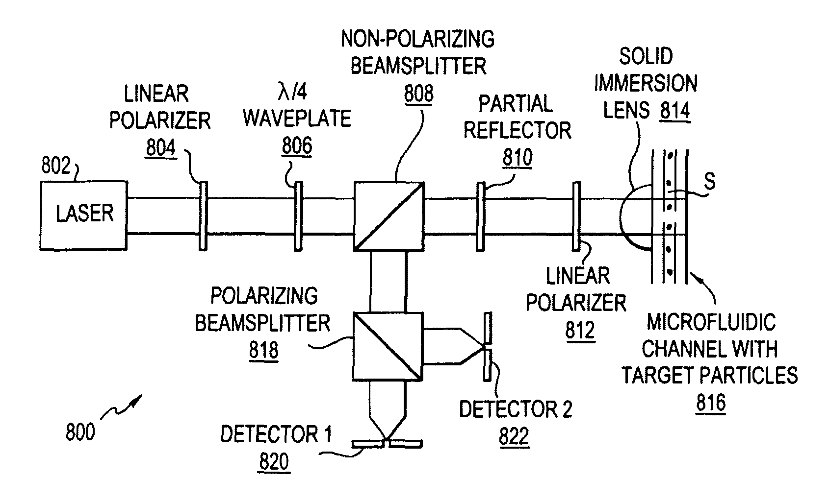
[0045]A preferred embodiment will be set forth in detail with reference to the drawings, in which like reference numerals refer to like elements or steps throughout.

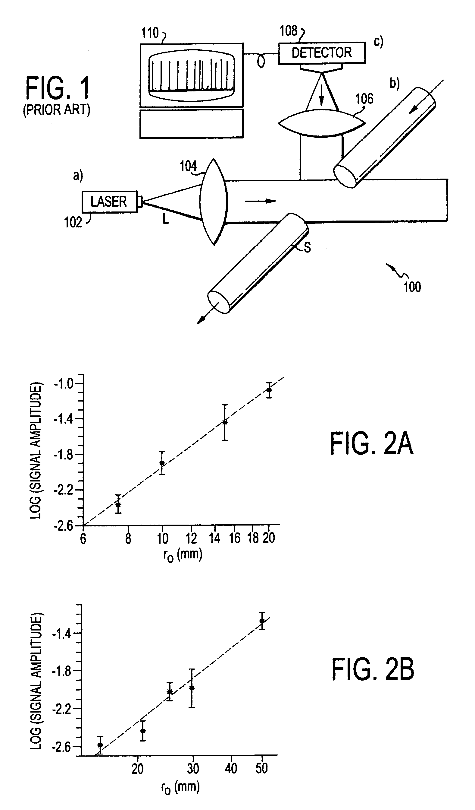
[0046]Based on the discussion above, to increase the detection sensitivity for nanoscale particles one needs to determine a signal that exhibits a particle size dependence that scales weaker than R6. In our previous work we have laid out two strategies: 1) gradient force detection and 2) interferomeric detection. Both approaches reduce the signal dependence from |α|2 to |α|, thereby making the signal dependent on R3. The gradient force based method monitors the influence of the field gradient ∇E2 of a strongly focused laser beam on the trajectory of a target particle, whereas the interferometric approach measures the field Escatt of the particle's scattered field as opposed to its intensity. The weaker particle size dependence has been verified in both schemes.

[0047]FIGS. 2A and 2B show the measured interferometric parti...


PUM


Abstract

A beam of coherent laser light with linear polarization oriented at 45 degrees to vertical is expanded, and passes through a quarter-wave plate with the fast axis oriented vertically, creating circularly polarized light. The light then passes through a non-polarizing 50 / 50 beamsplitter. A partial reflector then collinearly reflects a portion of the beam, which is used as the reference beam. The transmitted light passes through a linear polarizer oriented at 45 degrees to vertical, and is focused via a lens onto the sample of interest. Light scattered from this region is re-collimated by the lens and the directed through the linear 45 degree polarizer and through the partial reflector, where it recombines with the reference beam. One use of the invention is to detect microparticles in water.

Description

REFERENCE TO RELATED APPLICATION[0001]The present application claims the benefit of U.S. Provisional Patent Application No. 60 / 960,072, filed Sep. 14, 2007. The present invention is an improvement to the inventions disclosed and claimed in U.S. patent application Ser. Nos. 11 / 710,976, filed Feb. 27, 2007, titled “MULTI-COLOR HETERODYNE INTERFEROMETRIC APPARATUS AND METHOD FOR SIZING NANOPARTICLES,” and 11 / 417,254, filed May 4, 2006, titled “APPARATUS AND METHOD FOR SIZING NANOPARTICLES BASED ON OPTICAL FORCES AND INTERFEROMETRIC FIELD DETECTION.” The disclosures of all of the above-cited applications are hereby incorporated by reference in their entireties into the present disclosure.STATEMENT OF GOVERNMENT INTEREST[0002]The work leading to the present invention was funded in part by AFOSR Agreement No. F-49620-03-1-0379. The government has certain rights in the invention.FIELD OF THE INVENTION[0003]The present invention is directed to an interferometer for nano-particle detection, ...

Claims


Application Information

Patent Timeline
Patent Type & Authority Patents(United States)
IPC IPC(8): G01B9/02
CPCB82Y35/00G01N15/1456G01N2015/0038
Inventor NOVOTNY, LUKASDEUTSCH, BRADLEY
Owner UNIVERSITY OF ROCHESTER
Why Eureka
Try Eureka