
Composite coating device and method of forming overcoat on magnetic head using the same

a technology of magnetic head and coating device, which is applied in the direction of maintaining head carrier alignment, manufacturing head surface, instruments, etc., can solve the problem of difficult to obtain high recording density

Inactive Publication Date: 2011-01-04
SHIMADZU CORP
View PDF24 Cites 2 Cited by
  • Summary
  • Abstract
  • Description
  • Claims
  • Application Information

AI Technical Summary

Benefits of technology

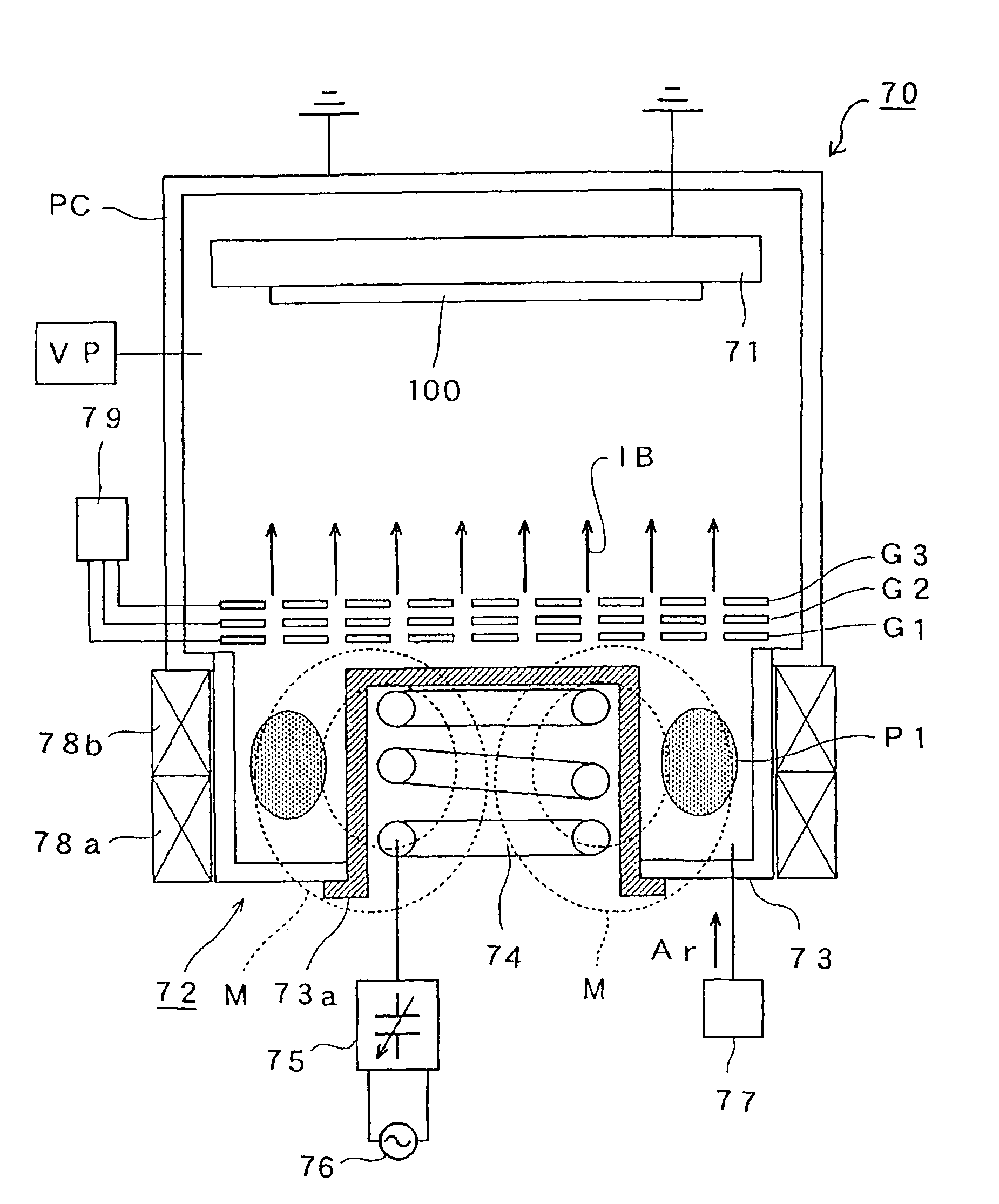
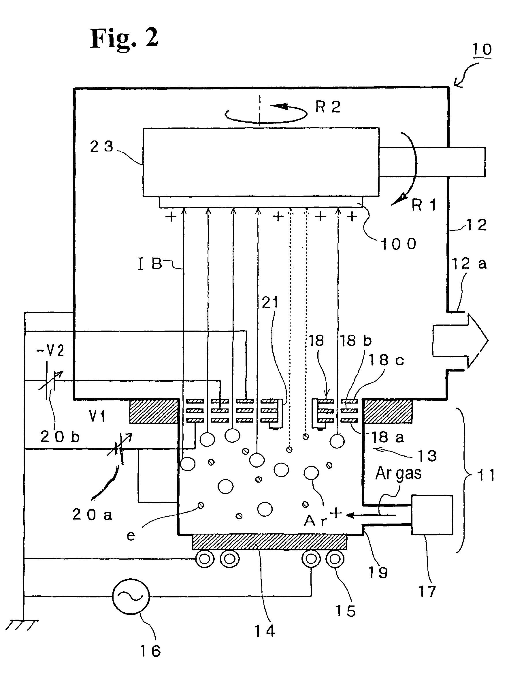
[0010]According to a third aspect of the present invention, in the composite coating devices in the first and second aspects, an ion beam etching device includes an ion source provided with an electrode for obtaining ions having a first grid with positive potential and a second grid with negative potential; and a communicating portion for eliminating an effect of the potential of the second grid relative to an electron in a plasma production area and for communicating a plasma production area with an outside of the plasma production area. The ion beam etching device may be provided with a dielectric block for adjusting a plasma density distribution at a plasma production portion. The ion beam etching device may also be provided with a high-frequency induction coupled plasma source including an electric insulation dividing wall projecting into the plasma production area and separating the plasma production chamber from outside, and an excitation coil provided in an outer concave portion of the electric insulation dividing wall.

Problems solved by technology

When the sputter etching is used for the pretreatment process, there is the following problem.
As a result, the flight height increases, thereby making it difficult to obtain high recording density.

Method used


Image

  • Composite coating device and method of forming overcoat on magnetic head using the same
  • Composite coating device and method of forming overcoat on magnetic head using the same
  • Composite coating device and method of forming overcoat on magnetic head using the same

Examples


Embodiment Construction

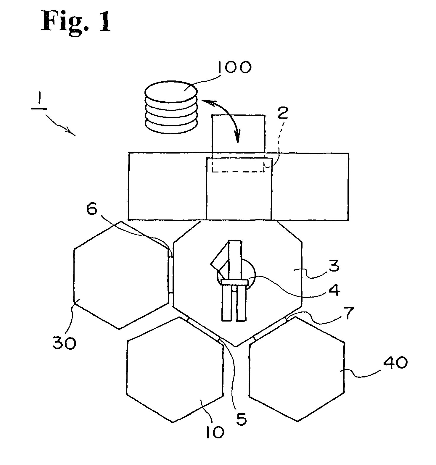
[0028]Hereunder, embodiments of the present invention will be described with reference to the accompanying drawings. FIG. 1 is a schematic view showing a structure of a composite coating device according to an embodiment of the present invention.

[0029]As shown in FIG. 1, a composite coating device 1 includes a cassette chamber 2 wherein a substrate 100 with a plurality of magnetic heads arranged thereon is taken in and out; a conveyance chamber 3 wherein the substrate 100 is transferred; an IBE device 10 for performing ion beam etching (hereinafter, referred to as IBE); a MSD device 30 for performing magnetron sputter deposition (hereinafter, referred to as MSD); and an ECR-CVD device 40 for performing electron cyclotron resonance plasma chemical vapor epitaxy (hereinafter, referred to as ECR-CVD). The conveyance chamber 3 is connected with the IBE device 10, the MSD device 30, and the ECR-CVD device 40 through gates 5, 6 and 7, respectively. The substrate 100 inside the conveyance ...


PUM

PropertyMeasurementUnit
depthaaaaaaaaaa
frequencyaaaaaaaaaa
thicknessaaaaaaaaaa

Abstract

A composite coating device includes first to third processing chambers. The first processing chamber performs an ion beam etching as a pretreatment process in which an ion beam is irradiated on a surface of a magnetic head at a predetermined angle and the surface is removed for a predetermined depth. The second processing chamber performs a magnetron sputter deposition as a shock absorbing coating formation process in which a shock absorbing coating is formed on the pretreated surface. The third processing chamber performs an electron cyclotron resonance plasma chemical vapor epitaxy or a cathode arc discharge deposition as an overcoat formation process in which an overcoat is formed on the shock absorbing coating. A preparation chamber communicates with the first to third processing chambers through opening and closing devices for transferring the magnetic head.

Description

BACKGROUND OF THE INVENTION AND RELATED ART STATEMENT[0001]The present invention relates to a composite coating device for forming a composite coating on a magnetic head and a method of forming a composite coating on a magnetic head.[0002]In a magnetic storage device, a magnetic head is used to record and retrieve data stored in a magnetic storage media. For example, in a hard drive (HD) magnetic storage device in which data is recorded on a magnetic disk, when a magnetic head records and retrieves (access) data, the magnetic head rises from a disk surface only for a predetermined distance. When the magnetic head does not access data, the magnetic head lands on the disk surface in a so-called CSS (contact start and stop) mechanism.[0003]As described above, when the magnetic head does not access data, the magnetic head receives a shock from the disk. The magnetic head also receives a corrosive action through atmospheric moisture and the like, so that wear resistance and corrosion res...

Claims


Application Information

Patent Timeline
Patent Type & Authority Patents(United States)
IPC IPC(8): C25B9/00C23C16/00C25B11/00C25B13/00C23C14/00C23C14/02C23C14/32C23C14/56C23C16/511C23C16/54G11B5/10G11B5/127G11B5/187G11B5/255G11B5/31G11B5/40G11B5/60
CPCC23C14/022C23C14/325C23C14/568C23C16/511C23C16/54G11B5/127G11B5/187G11B5/255G11B5/102G11B5/3106G11B5/40
Inventor KONISHI, YOSHIYUKIUEDA, MASAHIROSUZUKI, MASAYASU
Owner SHIMADZU CORP
Learn More