
Method of storing and generating hydrogen for fuel cell applications

a fuel cell and hydrogen storage technology, applied in the field of hydrogen storage and generation methods, can solve the problems of unsafe, unportable, and high cost of hydrogen storage containers, and achieve the effect of prolonging the shelf life of metal hydride and being convenient to deliver

Inactive Publication Date: 2010-12-28
NANOTEK INSTR GRP LLC
View PDF14 Cites 8 Cited by
  • Summary
  • Abstract
  • Description
  • Claims
  • Application Information

AI Technical Summary

Benefits of technology

[0025]The present invention provides a hydrogen gas storage and supply method wherein hydrogen is stored as part of a metal hydride or chemical hydride and hydrogen is generated when the hydride is brought to contact and react with a liquid reactant such as water or alcohol. An important element in the method is the utilization of a reaction-controlling agent (in the solid state), such as an acid or a metal salt, to accelerate (or delay) the reaction between a hydride and a liquid reactant. This accelerator is essential to providing an adequate hydrogen generation rate for the operation of a fuel cell for a motorcycle, wheelchair, golf cart, automobile, etc. For vehicular applications, a fuel cell could consume hydrogen fuel at a rate of 10 grams to 1 kilogram per hour. Surprisingly, the accelerator makes it possible to produce an adequate amount of hydrogen without using an expensive catalyst such as nano-scaled metal particles (Pt and Ru, etc.). An inexpensive and environmentally benign acid such as citric acid can be used instead.
[0027]Another preferred embodiment of the present invention is a hydrogen gas storage and supply method, comprising: (a) providing a hydrogen fuel source comprising a metal hydride or chemical hydride dissolved and / or dispersed in a liquid medium; and (b) delivering a desired amount of a reaction-controlling agent in a solid state to contact with the hydrogen fuel source to produce hydrogen gas. Preferably, the hydrogen fuel source further comprises a stabilizing agent selected from LiOH, NaOH, KOH, RbOH, CsOH, Be(OH)2, Mg(OH)2, Ca(OH)2, Sr(OH)2, Ba(OH)2, or a combination thereof to extend the shelf life of a metal hydride or chemical hydride that is commercially available in a solution form. The hydrogen production process is initiated or accelerated when a controlled amount of the reaction-controlling agent (preferably in a solid powder form) is delivered to contact the liquid medium containing the hydride. One advantage of this method is the notion that the reaction-controlling agent in a solid form can be conveniently delivered to accelerate the hydrogen generation process without having to use an expensive catalyst such as platinum or ruthenium.

Problems solved by technology

A major drawback in the utilization of hydrogen-based fuel cells for powering vehicles or microelectronic devices is the lack of an acceptable lightweight, high-capacity, and safe hydrogen storage medium.
However, the containers for storing the liquefied hydrogen are made of very expensive super-insulating materials.(b) The compressed gas storage approach is usually applied in underground supply systems, similar to a network of natural gas pipelines.
This is an economical and simple approach, but it is unsafe and not portable.
Compressed hydrogen gas in a large steel tank could be an explosion hazard.(c) The cryo-adsorbing storage approach involves moderate weight and volume.
The disadvantages of this approach are related to the low capacity and the cryogenic temperature required, which makes it necessary to use expensive super-insulated containers.(d) The metal hydrides can store H2 via a chemical reaction of H+M≈M−H, wherein M is a selected metal element.
This renders the container for the metal hydride too heavy and expensive, and limits the practical exploitation of these systems for portable electronic and mobility applications.
Typically, these reactions are not easily reversible on-board a vehicle.
This prior art approach has the following major drawbacks: (1) the need to use an expensive catalyst such as platinum; (2) a limited solubility of NaBH4 in water at a given temperature and the need to include water in the fuel container, resulting in a reduced amount of NaBH4 that can be accommodated in a container (hence, a low energy density); and (3) the need to use a caustic ingredient that makes the handling of the fuel more difficult (corrosion-resistant container required) and complicates the process for recovering the spent fuel such as NaBO2.
There are still problems associated with this approach.
As the scale layer grows progressively thicker, it gets increasingly more difficult for the water to penetrate through the metaborate crust to reach the unreacted NaBH4 fuel below, resulting in a decreased hydrogen production rate.
Nano catalyst particles such as platinum, ruthenium, and cobalt are very expensive.
They are also difficult to recover and reuse once they become part of the spent fuel.
The above review indicates that the hydrogen storage technology still has the following major barriers to overcome: (1) low H2 storage capacity, (2) difficulty in storing and releasing H2 (normally requiring a high temperature to release and a high pressure to store), (3) high costs, (4) potential explosion danger, (5) need to utilize expensive catalysts, and (6) utilization of caustic solution.
However, their study did not utilize (nor did they suggest explicitly or implicitly the utilization of) a dry, solid acid powder in an admixture with solid sodium borohydride, which is found by us to be a very convenient form of reactant delivery.
Furthermore, the study of Kaufman, et al. was limited to sodium borohydride, not including any other type of chemical hydride or any simple metal hydride.
They also failed to use environmentally benign acids or metal salts to accelerate the hydrogen generation reaction.
For instance, they used perchloric acid which is undesirable.

Method used


Image

  • Method of storing and generating hydrogen for fuel cell applications
  • Method of storing and generating hydrogen for fuel cell applications
  • Method of storing and generating hydrogen for fuel cell applications

Examples


Embodiment Construction

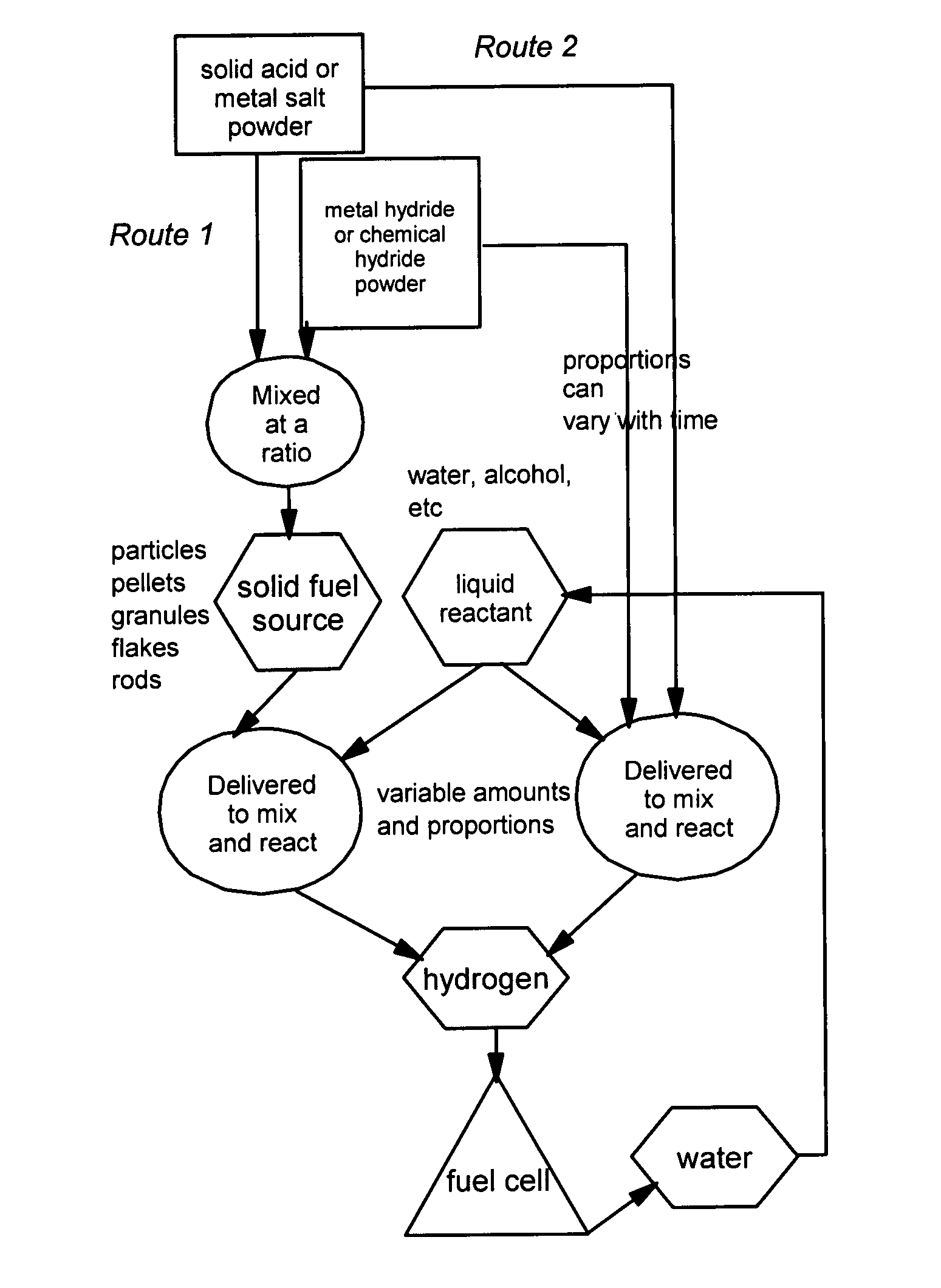
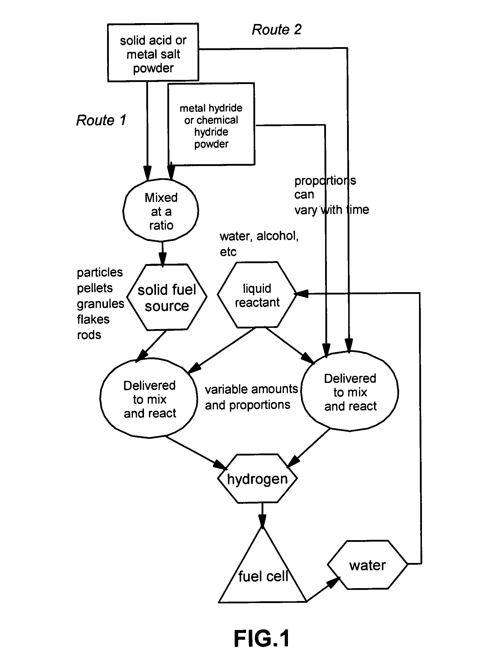
[0033]The present invention provides a hydrogen gas storage and supply method wherein hydrogen is stored as part of a metal hydride or chemical hydride and hydrogen is released when the hydride is allowed to contact and react with a liquid reactant such as water or alcohol. Typically, the reaction between a hydride and a liquid reactant is accelerated by a reaction-controlling agent such as an acid or a metal salt in a solid state, without using an expensive catalyst such as nano-scaled metal particles. In some cases, the reaction-controlling agent serves to prevent or slow down an otherwise violent reaction. The procedures are schematically shown in FIG. 1, which indicates two preferred routes to follow:

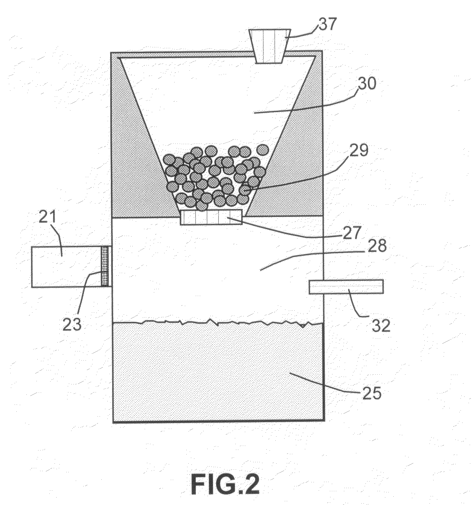
[0034]In one preferred route (Route 1), the hydride and the reaction-controlling agent are pre-mixed at a desired proportion to make multiple particles in a form of beads, pellets, granules, flakes, capsules, or any other solid powder form. As illustrated in FIG. 2, solid hydride po...


PUM

PropertyMeasurementUnit
volumesaaaaaaaaaa
operating temperatureaaaaaaaaaa

Abstract

A preferred embodiment of the present invention is a hydrogen gas storage and supply method, comprising (a) providing a dry, solid-state hydrogen fuel source comprising a solid metal hydride or chemical hydride and a reaction-controlling agent in a solid state, wherein the hydride and the reaction-controlling agent are mixed at a desired proportion; and (b) delivering a desired amount of a liquid reactant to contact and react with a desired amount of the solid-state fuel source to produce hydrogen gas continuously or intermittently on demand, responsive to the needs of a fuel cell.

Description

FIELD OF THE INVENTION[0001]This invention relates to a hydrogen storage and generation method and more particularly to a method of safely storing hydrogen in a hydride form and generating hydrogen on demand to feed hydrogen to a power-generating device such as a fuel cell or a hydrogen combustion engine.BACKGROUND OF THE INVENTION[0002]A major drawback in the utilization of hydrogen-based fuel cells for powering vehicles or microelectronic devices is the lack of an acceptable lightweight, high-capacity, and safe hydrogen storage medium. Four conventional approaches to hydrogen storage are currently in use: (a) liquid hydrogen, (b) compressed gas, (c) cryo-adsorption, and (d) metal hydride or chemical hydride storage systems. A brief description of these existing approaches is given below:[0003](a) The liquid hydrogen storage approach offers good solutions in terms of technology maturity and economy, for both mobile storage and large-volume storage systems with volumes ranging from ...

Claims


Application Information

Patent Timeline
Patent Type & Authority Patents(United States)
IPC IPC(8): C01B3/06
CPCF17C11/005H01M8/04208H01M8/065F17C2221/012Y02E60/321Y02E60/50Y02E60/32
Inventor FULLER, IAN M.JANG, BOR Z.
Owner NANOTEK INSTR GRP LLC
Learn More