
Oxide superconductor and method for producing the same

a superconductor and superconductor technology, applied in the direction of superconducting magnets/coils, magnetic bodies, liquid/solution decomposition chemical coatings, etc., can solve the problems of high production cost, difficult control of production conditions, and difficult to obtain good superconductors

Active Publication Date: 2010-11-16
KK TOSHIBA
View PDF10 Cites 10 Cited by
  • Summary
  • Abstract
  • Description
  • Claims
  • Application Information

AI Technical Summary

Benefits of technology

The present invention provides an oxide superconductor film that has a specific composition and structure, which allows for its formation on a substrate. The film has a thickness of 350 nm or more and contains at least one metal selected from yttrium and lanthanoid metals, excluding cerium, praseodymium, and promethium. The film also contains barium and copper, with a specific amount of residual carbon and fluorine. The film can be divided into regions with different thicknesses and atomic ratios of copper, fluorine, oxygen, and carbon between them. The invention also provides a method for producing the oxide superconductor film by coating a substrate with a coating solution containing metal salts and an organic substance with a specific ratio of fluorine and hydrogen, and then calming, firing, and oxygen-annealing the gel film. The technical effects of the invention include the formation of a stable and high-quality oxide superconductor film on a substrate with a specific composition and structure, which can be used for various applications such as magnetic resonance imaging (MRI) and power transmission.

Problems solved by technology

However, production conditions are hard to be controlled in the processes since all the deposition conditions must be controlled at once, which has been revealed that good superconductors can hardly be obtained.
However, the EB processing involves a problem of high production cost.
While much effort has been made in order to reduce harmful residual carbon in the production of the Y-based superconductor by the MOD method, there is no effective method for reducing the residual carbon.
However, while the TFA-MOD method has a large advantage that a superconductor exhibiting excellent superconducting properties may be produced with a low production cost, it is disadvantageously difficult to increase the thickness of the film.
However, it has been known that fatal degradation in superconducting properties is caused due to an increased amount of residual carbon when the thickness of the superconductor is increased by repeated coatings in the MOD method.
Accordingly, a quite long time of heat treatment is necessary for increasing the thickness of the superconductor when coating is repeated in the TFA-MOD method.
Homogeneity of the superconducting film is lost due to local crystallization when the film experiences many times of heat hysteresis, and the quality of the film is gradually degraded.
However, since intermediate oxide layers are formed by repeated coatings as described above, adjustment of filter characteristics becomes quite difficult due to the oxide as a cause of loss to make it difficult to produce a sharp-cut filter.
However, residual carbon originating from the added organic compound is a problem in the MOD method.
On the other hand, it has been found in recent years that, when the same method is used in the TFA-MOD method, residual fluorine is problematic rather than residual carbon by virtue of the action of the carbon expulsion scheme.
However, it has been found that a minute amount of a texture of a Y-based superconductor in which fluorine compounds are mixed is formed by keeping the superconductor under the firing condition for a long period of time.
The fluorine compound is recrystallized into barium fluoride during cooling, which leads to disturbance of crystal orientation.
However, since the solution used by Rupich et al is not a high-purity solution prepared by a Solvent-Intro-Gel method, it may be supposed that a certain amount of acetate salt remains already, which possibly increases the amount of residual fluorine.

Method used


Image

  • Oxide superconductor and method for producing the same
  • Oxide superconductor and method for producing the same
  • Oxide superconductor and method for producing the same

Examples


example 1

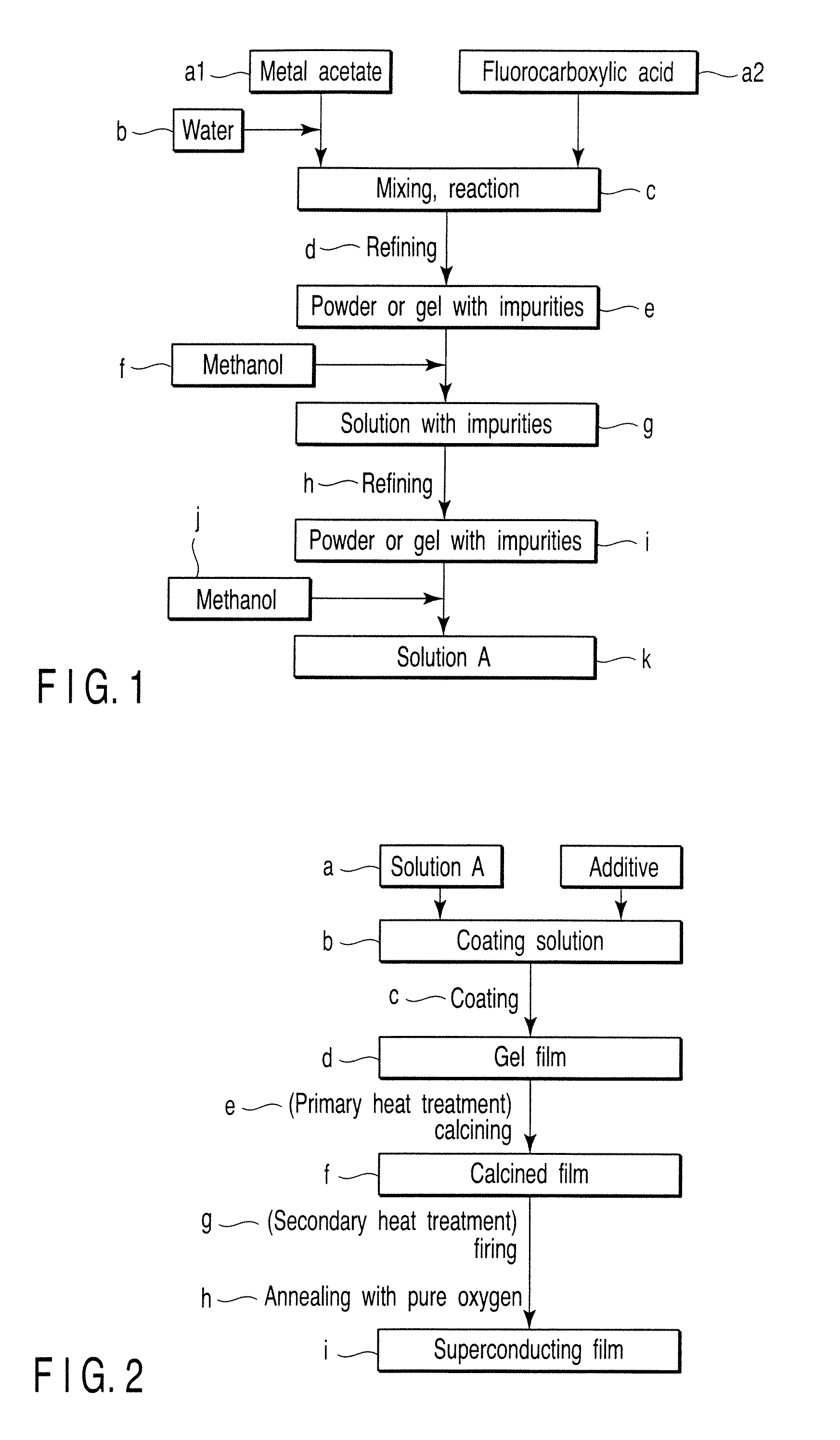
[0071]Powders of hydrates of Y(OCOCH3)3, Ba(OCOCH3)2 and Cu(OCOCH3)2 were dissolved in ion-exchange water, and each solution was mixed with an equimolar amount of CF3COOH for reaction with stirring. These solutions were mixed so that molar ratio of metal ions is 1:2:3 to obtain a mixed solution. The mixed solution obtained was placed in a round-bottom flask, and was allowed to react for 12 hours in vacuum with purification using a rotary evaporator to obtain a semi-transparent blue gel or sol.

[0072]A solution, which was obtained by completely dissolving the gel or sol by adding methanol (FIG. 1f) corresponding to 100 times the weight of the gel or sol, was purified in vacuum for 12 hours using a rotary evaporator to obtain a semi-transparent blue gel or sol.

[0073]The gel or sol obtained was dissolved again in methanol (FIG. 1j), and was diluted using a measuring flask to obtain coating solution A with a concentration of 1.52M as reduced into the concentration of metal ions.

[0074]Coa...

example 2

[0085]Powders of hydrates of Y(OCOCH3)3, Ba(OCOCH3)2 and Cu(OCOCH3)2 were dissolved in ion-exchange water, and each solution was mixed with an equimolar amount of CF3COOH for reaction with stirring. These solutions were mixed so that the molar ratio of metal ions was 1:2:3 to obtain a mixed solution. The mixed solution obtained was placed in a round-bottom flask, and was allowed to react for 12 hours in vacuum with purification using a rotary evaporator to obtain a semi-transparent blue gel or sol.

[0086]A solution, which was obtained by completely dissolving the gel or sol by adding methanol (FIG. 1f) corresponding to 100 times the weight of the gel or sol, was purified in vacuum for 12 hours using a rotary evaporator to obtain a semi-transparent blue gel or sol.

[0087]The gel or sol obtained was dissolved again in methanol (FIG. 1j), and was diluted using a measuring flask to obtain coating solution 2A with a concentration of 1.52M as reduced into the concentration of metal ions.

[00...

example 3

[0099]Powders of hydrates of Y(OCOCH3)3, Ba(OCOCH3)2 and Cu(OCOCH3)2 were dissolved in ion-exchange water, and each solution was mixed with an equimolar amount of CF3COOH for reaction with stirring. These solutions were mixed so that molar ratio of metal ions is 1:2:3 to obtain a mixed solution. The mixed solution obtained was placed in a round-bottom flask, and was allowed to react for 12 hours in vacuum with purification using a rotary evaporator to obtain a semi-transparent blue gel or sol.

[0100]A solution, which was obtained by completely dissolving the gel or sol by adding methanol (FIG. 1f) corresponding to 100 times the weight of the gel or sol, was purified in vacuum for 12 hours using a rotary evaporator to obtain a semi-transparent blue gel or sol.

[0101]The gel or sol obtained was dissolved again in methanol (FIG. 1j), and was diluted using a measuring flask to obtain coating solution 3A with a concentration of 2.31M as reduced into the concentration of metal ions. Accordi...


PUM

PropertyMeasurementUnit
thicknessaaaaaaaaaa
thicknessaaaaaaaaaa
lengthaaaaaaaaaa

Abstract

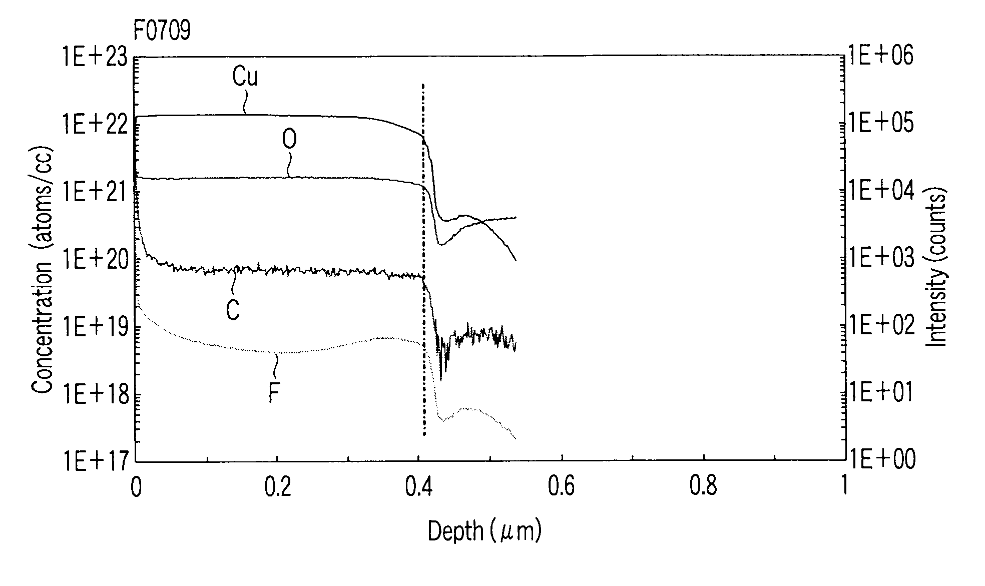
An oxide superconductor film formed on a substrate includes an oxide containing at least one metal M selected from the group consisting of yttrium and lanthanoid metals, provided that cerium, praseodymium, and promethium are excluded, and barium and copper, in which the film has an average thickness of 350 nm or more, an average amount of residual carbon of 3×10¹⁹ atoms / cc or more, and an amount of residual fluorine in a range of 5×10¹⁷ to 1×10¹⁹ atoms / cc, and in which, when divided the film into a plurality of regions from a surface of the film or from an interface between the film and the substrate, each region having a thickness of 10 nm, atomic ratios of copper, fluorine, oxygen and carbon between two adjacent regions are in a range of ⅕ times to 5 times.

Description

CROSS-REFERENCE TO RELATED APPLICATIONS[0001]This application is based upon and claims the benefit of priority from prior Japanese Patent Application No. 2006-324620, filed Nov. 30, 2006, the entire contents of which are incorporated herein by reference.BACKGROUND OF THE INVENTION[0002]1. Field of the Invention[0003]The present invention relates to an oxide superconductor and a method for producing the same.[0004]2. Description of the Related Art[0005]High critical-current oxide superconductor materials that have been developed in recent years are expected to be usefully applied, for example, to fusion reactors, magnetically levitated trains, particle accelerators, magnetic resonance imaging apparatuses (MRI) and microwave filters, and some of these technologies have been already used in practical fields.[0006]Major oxide superconductors are bismuth-based, yttrium-based and thallium-based superconductors. Of these materials, yttrium-based superconductors have been attracting much at...

Claims


Application Information

Patent Timeline
Patent Type & Authority Patents(United States)
IPC IPC(8): H01B12/00H01L39/12
CPCC23C18/1216C23C18/1254C23C18/1295H01L39/2425Y10T428/24975Y10T29/49014Y10T428/26H10N60/0324
Inventor ARAKI, TAKESHI
Owner KK TOSHIBA
Learn More