Semiconductor device and manufacturing method of the same
a technology of semiconductors and manufacturing methods, applied in the direction of semiconductor devices, basic electric elements, electrical equipment, etc., can solve the problems of increasing complicated manufacturing process, so as to increase the manufacturing cost, and increase the number of steps
- Summary
- Abstract
- Description
- Claims
- Application Information
AI Technical Summary
Benefits of technology
Problems solved by technology
Method used
Image
Examples
embodiment mode 1
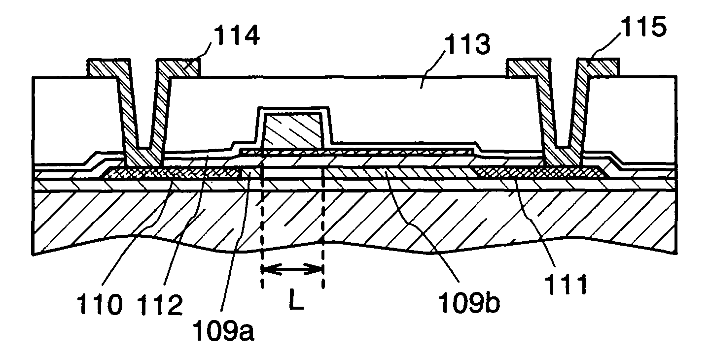
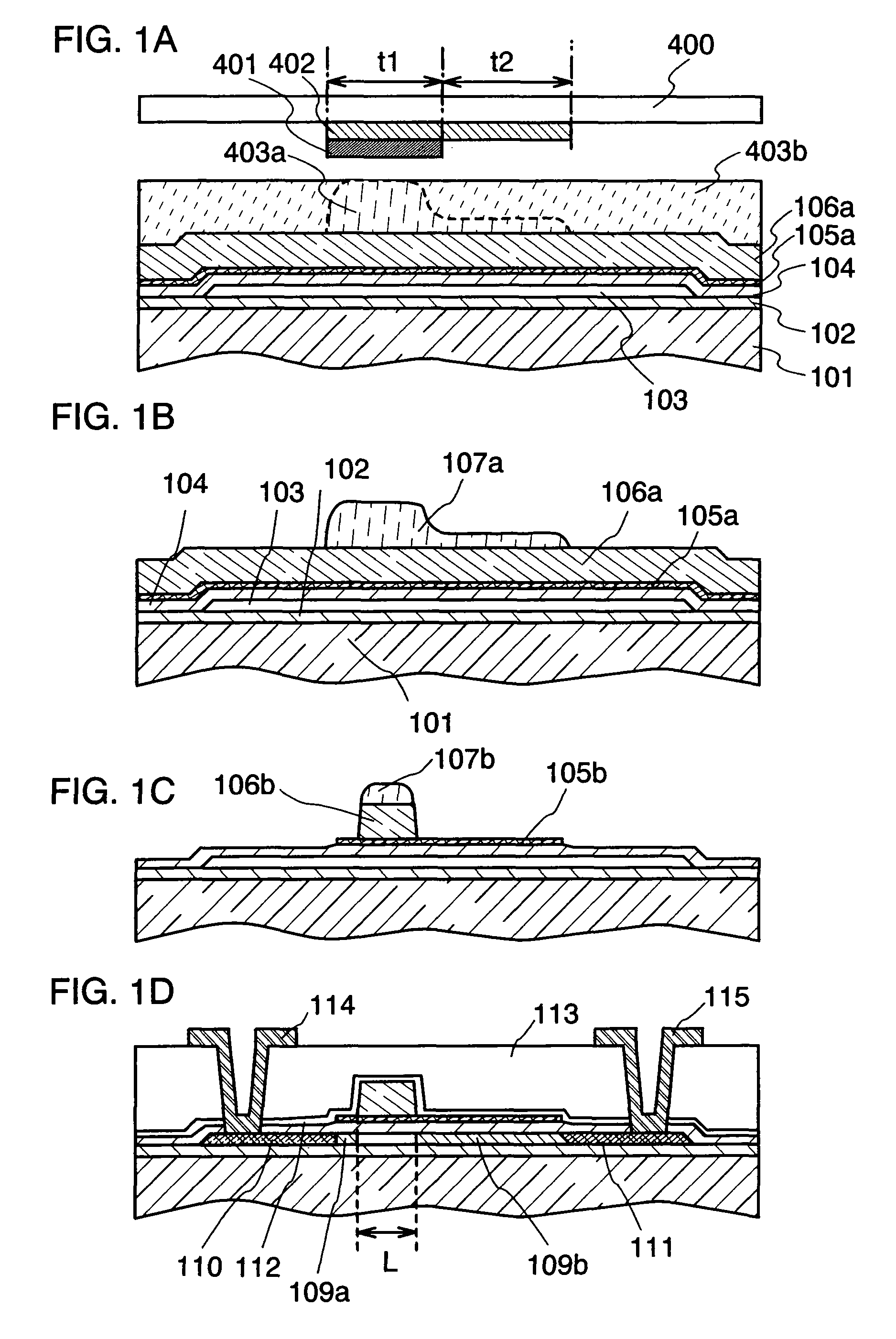
[0052]This embodiment mode describes a process for forming low-concentration impurity regions having different widths respectively on both sides of a channel forming region in a self-aligned manner by using a gate electrode of a TFT as a mask in ion-doping.
[0053]First, a first insulating film (a base insulating film) 102 is formed over a substrate 101 having an insulating surface. As the substrate 101 having an insulating surface, a light-transmitting substrate such as a glass substrate, a crystallized glass substrate, or a plastic substrate can be used. In the case where a thin film transistor to be formed is applied to a top emission light-emitting display device or a reflective liquid crystal display device, a ceramic substrate, a semiconductor substrate, a metal substrate, or the like can also be used.
[0054]As the first insulating film 102, a single layer or a stacked-layer of an insulating film such as a silicon oxide film, a silicon nitride film, or a silicon oxynitride (SiOxN...
embodiment mode 2
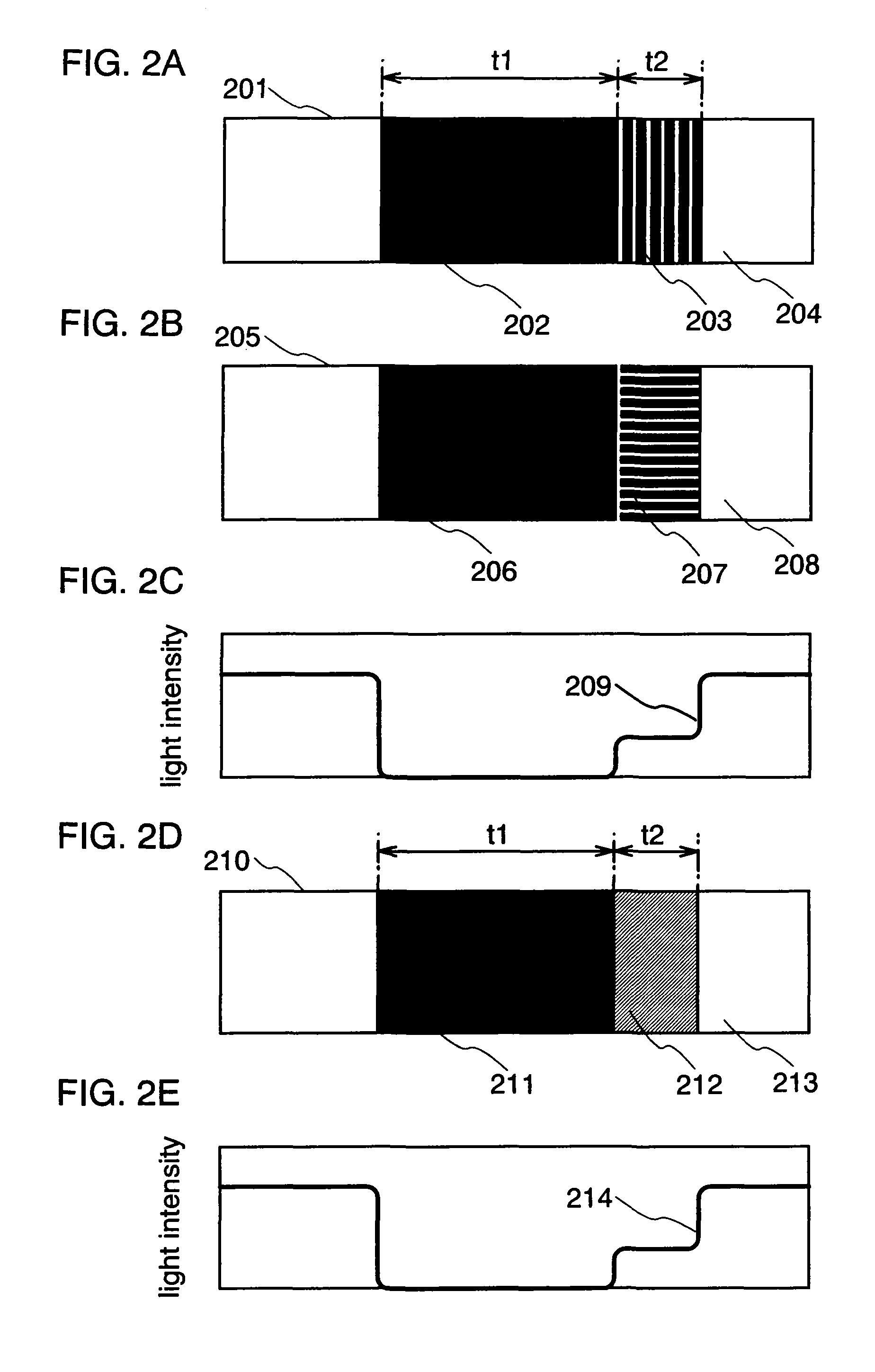
[0103]In this embodiment mode, an exposure mask provided with an auxiliary pattern having a light intensity reduction function formed of a diffraction grating pattern or a semi-transparent film, which is used in Embodiment Mode 1, is described with reference to FIGS. 2A to 2E.
[0104]Note that FIG. 1A is a cross-sectional view of an exposure mask. Similarly, also in FIGS. 2A to 2E, the width of a light shielding portion is denoted by t1 and the width of a portion provided with an auxiliary pattern is denoted by t2.
[0105]As specific examples of the auxiliary pattern, FIGS. 2A and 2B show part of top-plane views of an exposure mask provided with a diffraction grating pattern having a slit portion formed of a line and a space at or below the resolution limit of an exposure apparatus. Diffraction grating pattern is a pattern in which at least one pattern of a slit, a dot, or the like is provided. In the case where a plurality of patterns of a slit, a dot, or the like is provided, they may...
embodiment mode 3
[0112]A method for forming the conductive stacked-layer pattern described in Embodiment Mode 1 is not particularly limited. Here, an example of forming a conductive stacked-layer pattern by changing the etching condition several times during a process is described with reference to FIGS. 3A to 3F.
[0113]First, similarly to Embodiment Mode 1, a resist pattern 307a is formed over a second conductive layer 306a. FIG. 3A corresponds to FIG. 1B.
[0114]Note that in FIG. 3A, over a substrate 301, a first insulating film (base insulating film) 302, a semiconductor layer 303, and a second insulating film (gate insulating film) 304 are formed, and over that, a first conductive layer 305a and the second conductive layer 306a are formed.
[0115]Then, etching is performed in a first etching condition so that the resist pattern 307b and the second conductive layer 306b are formed with a shape shown in FIG. 3B. A tapered portion is formed in a part of the second conductive layer 306b in the first etch...
PUM
 Abstract
Description
Claims
Application Information
 - R&D
- Intellectual Property
- Life Sciences
- Materials
- Tech Scout
- Unparalleled Data Quality
- Higher Quality Content
- 60% Fewer Hallucinations
Browse by: Latest US Patents, China's latest patents, Technical Efficacy Thesaurus, Application Domain, Technology Topic, Popular Technical Reports.
© 2025 PatSnap. All rights reserved.Legal|Privacy policy|Modern Slavery Act Transparency Statement|Sitemap|About US| Contact US: help@patsnap.com


