Optical particle sensor with exhaust-cooled optical source
a technology of optical source and optical particle sensor, which is applied in the field of optical particle sensing, can solve the problems of increasing process reliability, reducing process downtime, and generating a substantial amount of heat from optical sources that illuminate samples with high radiant power, so as to improve the operating life and performance of these components, reduce operating temperature, and reduce the effect of thermal managemen
- Summary
- Abstract
- Description
- Claims
- Application Information
AI Technical Summary
Benefits of technology
Problems solved by technology
Method used
Image
Examples
example 1
Plenum-Cooled Particle Sensor
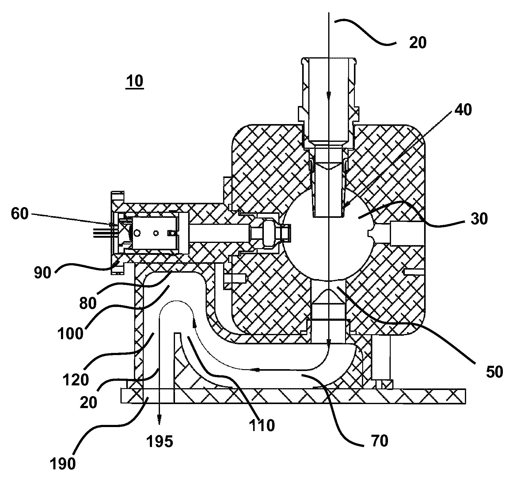
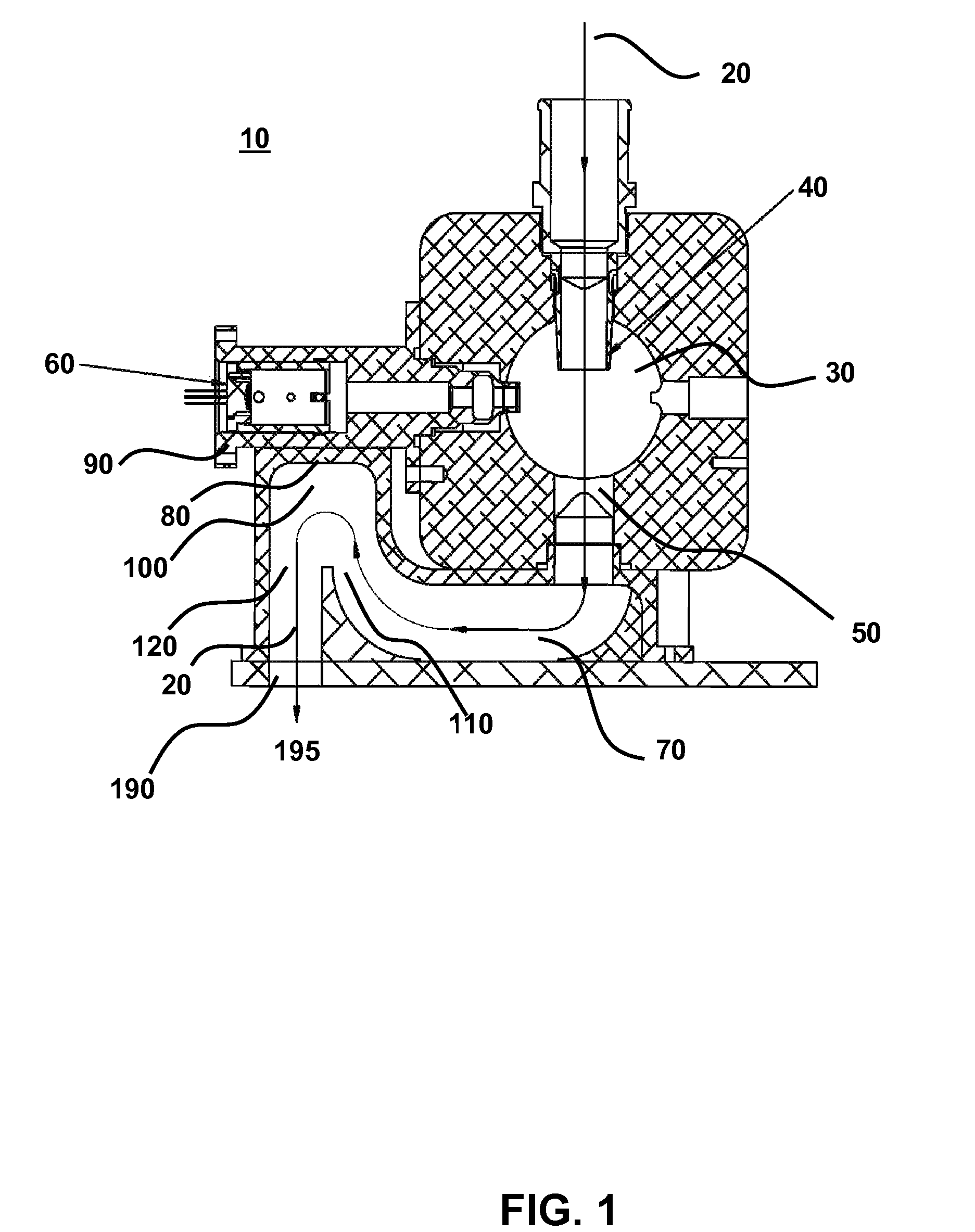
[0069]FIG. 1 is a schematic illustration of a particle sensor 10. Referring to FIG. 1, a fluid sample 20 is introduced to a sample chamber 30 at an inlet orifice 40. An optical source 60 illuminates fluid sample within chamber 30 and information is collected and analyzed to provide information about the status of fluid sample 20, as known in the art, such as scattering (forward and / or side), intensity, emission spectra, etc. Fluid sample flows out of the sample chamber 30 at an outlet orifice 50 and into outlet passage 70. Fluid sample exits the particle sensor 10 at an exhaust orifice or port 190. The general path of flowing fluid sample 20 is indicated by the arrow that transits the sample chamber 30 and outlet passage 70.
[0070]In this example, the outlet passage 70 further comprises a plenum 100 having a portion 80 in thermal contact with the optical source 60. In an embodiment, optical source 60 is positioned within the particle sensor 10 by a mounti...
example 2
Self-Contained Heat Sink Connected to Outlet Orifice
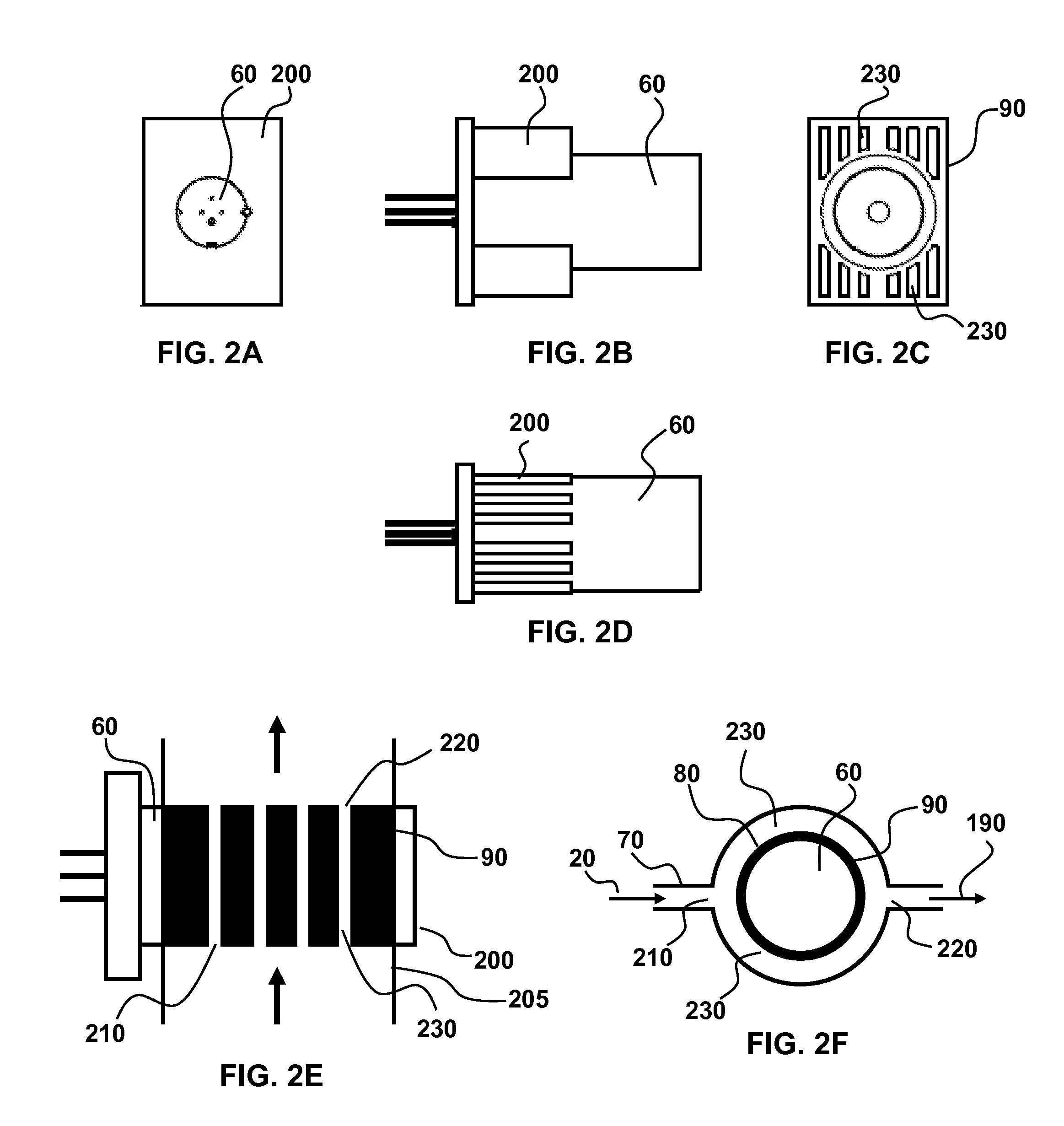
[0076]In an embodiment, a mounting element 90 with integral heat sink 200 provides cooling, (see, for example, FIGS. 2 and 5). A heat sink conduit 205 that provides sample fluid 20 to the heat sink 200 is connected to the sample chamber outlet orifice 50, the exhaust orifice 190, or to an outlet passage location between the outlet orifice 50 and exhaust orifice 190. To transport fluid sample to the heat sink, the heat sink passage is operably connected to the means for generating fluid flow, such as vacuum source or pump. In an aspect, the heat sink conduit comprises tubing, including flexible tubing, connected at one end for receiving sample fluid, such as to chamber outlet orifice 50, outlet passage 70 or exhaust orifice / port 190 and at the other end to inlet heat sink orifice 210 for introducing the fluid sample to the heat sink.
[0077]The heat sink optionally comprises one or more heat sink transfer passages 230 within the mount...
example 3
Airflow Cavity Within Mounting Assembly
[0080]An alternative cooling process relates to an airflow cavity positioned between the optical source 60 and optical source mount 90. In this aspect, air is routed into and out of the cavity using either tubing or a shaped air plenum. Although this aspect eliminates one thermal interface (e.g., the air coolant is in direct contact with the optical source), there is added complexity and cost that is minimized for the embodiments that use the sample fluid itself as the coolant. In this aspect, air is forced into the cavity by any means known in the art such as a fan or pump.
PUM
| Property | Measurement | Unit |
|---|---|---|
| power consumption | aaaaa | aaaaa |
| operating temperature | aaaaa | aaaaa |
| temperature | aaaaa | aaaaa |
Abstract
Description
Claims
Application Information
 - R&D
- Intellectual Property
- Life Sciences
- Materials
- Tech Scout
- Unparalleled Data Quality
- Higher Quality Content
- 60% Fewer Hallucinations
Browse by: Latest US Patents, China's latest patents, Technical Efficacy Thesaurus, Application Domain, Technology Topic, Popular Technical Reports.
© 2025 PatSnap. All rights reserved.Legal|Privacy policy|Modern Slavery Act Transparency Statement|Sitemap|About US| Contact US: help@patsnap.com


