Digital frequency synthesizer
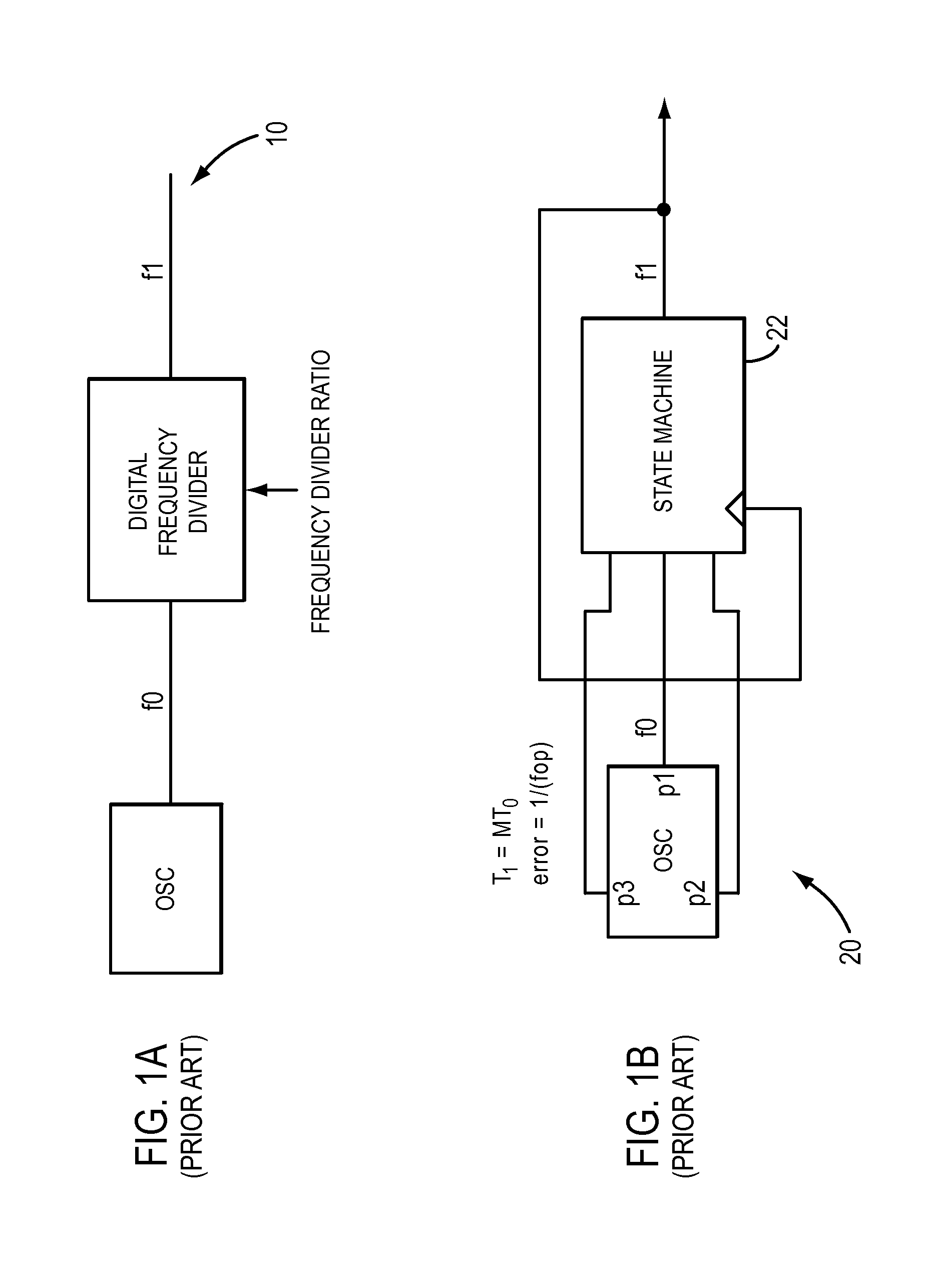
a digital frequency and frequency divider technology, applied in the field of digital frequency synthesis, can solve the problems of jitter and cumulative inaccuracy that limit the applications of such a frequency divider, and achieve the effect of greater output frequency accuracy
- Summary
- Abstract
- Description
- Claims
- Application Information
AI Technical Summary
Benefits of technology
Problems solved by technology
Method used
Image
Examples
embodiment 140
[0068]FIG. 2D shows a general embodiment 140 of the encoding decoding circuitry for use in the phase selection circuitry of the present invention. There is an initial stage for computing the parameter e, and then log2 p subsequent stages in the encoding block 142. The decoder decodes the log2 p binary signals, one from each of the stages.
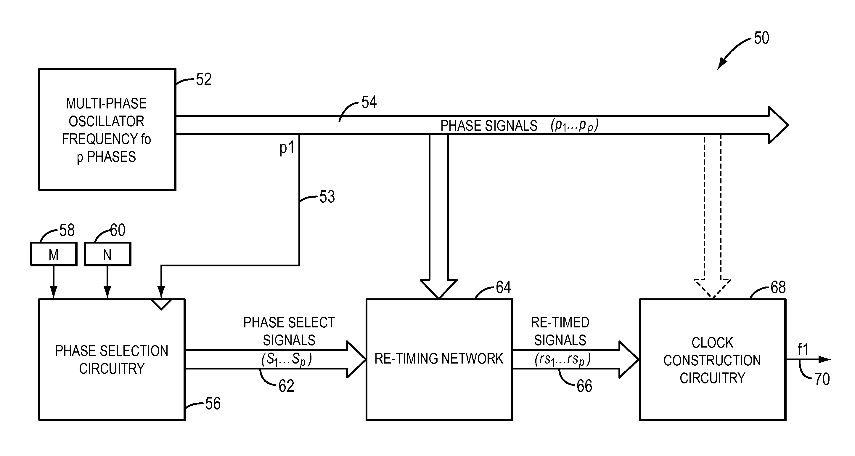
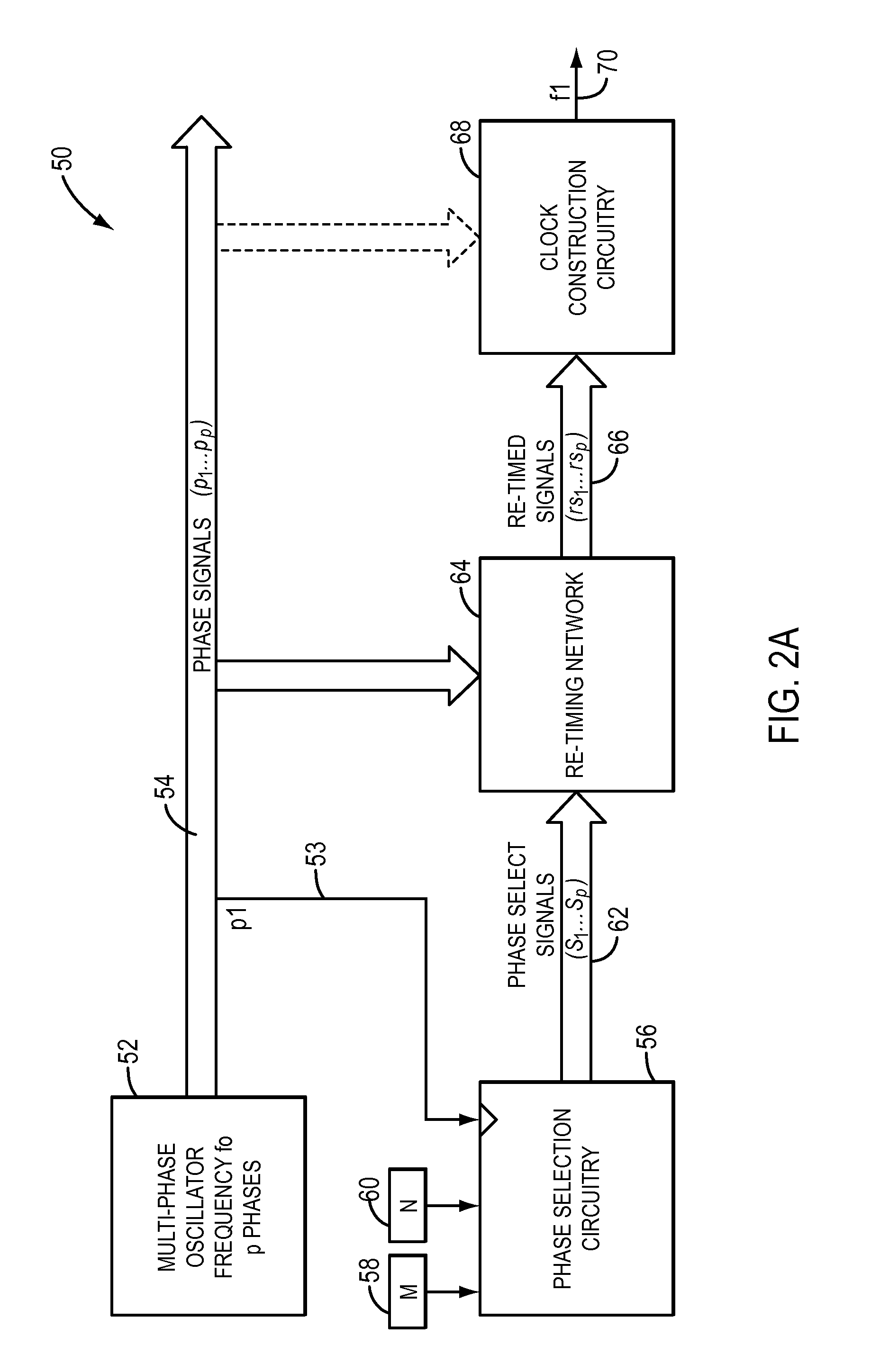
[0069]FIG. 4 shows an embodiment of the retiming network 64 of the present invention. The phase select signals 62 leaving the arithmetic unit are synchronous with the clock used for that unit, specifically one of the phases of the multi-phase clock (phase 153 is shown in FIG. 2A). In order to synthesize to the desired frequency, with the phase accuracy available from the multi-phase clock, these signals must be made synchronous with the phase signals they select, if active. The network 64 thus includes circuitry that receives each of the phase select signals 62 and re-clocks the signals to have the actual phase that the name of the phase select sign...
first embodiment
[0073]In FIG. 6B, the re-timed signals taken from the last rank of the retiming network 64 are simply OR'ed together in gate 244. This is not as accurate as the first embodiment, as there is a flip-flop delay between the actual phase signal of the multi-phase oscillator and the output, but may be acceptable in some circumstances.
[0074]FIG. 7 shows one of many applications 260 of the frequency synthesizer of the present invention. A multiphase clock such as a rotary traveling wave oscillator 262 is setup to provide and distribute multiple phases to a plurality of blocks 264, 266, 268, 270 on an integrated circuit. Each of the blocks, a PCI block 264, a Graphics Interface block 266, a Co-processor block 268, and a memory bus block 270, has a need for a different frequency of operation which may be optimal for the functions the block carries out. A PCI block 264 for example, may need to operate at 2.5 GHz, the Graphics Interface block 266 may need to operate at 8 GHz, the Co-processor ...
PUM
 Abstract
Description
Claims
Application Information
 - R&D
- Intellectual Property
- Life Sciences
- Materials
- Tech Scout
- Unparalleled Data Quality
- Higher Quality Content
- 60% Fewer Hallucinations
Browse by: Latest US Patents, China's latest patents, Technical Efficacy Thesaurus, Application Domain, Technology Topic, Popular Technical Reports.
© 2025 PatSnap. All rights reserved.Legal|Privacy policy|Modern Slavery Act Transparency Statement|Sitemap|About US| Contact US: help@patsnap.com


