
Method for forming tetragonal zirconium oxide layer and method for fabricating capacitor having the same

a zirconium oxide and tetragonal technology, applied in the direction of coatings, sustainable transportation, chemical vapor deposition coatings, etc., can solve the problem of difficult to obtain the zro2 layer with tetragonal structure, and achieve the effect of improving the dielectric property the tetragonality of the zro2 layer

Inactive Publication Date: 2010-08-10
SK HYNIX INC
View PDF15 Cites 11 Cited by
  • Summary
  • Abstract
  • Description
  • Claims
  • Application Information

AI Technical Summary

Benefits of technology

The method effectively forms a ZrO2 layer with a high dielectric constant and stable tetragonal structure at low temperatures, suitable for high-integration semiconductor devices, improving dielectric capacitance and energy band gap, enabling the development of advanced DRAM devices with smaller sizes.

Problems solved by technology

However, it is very difficult to obtain the ZrO2 layer with tetragonal structure because the tetragonal structure is a structure more stable at a high temperature than the monoclinic structure or the cubic structure.

Method used


Image

  • Method for forming tetragonal zirconium oxide layer and method for fabricating capacitor having the same
  • Method for forming tetragonal zirconium oxide layer and method for fabricating capacitor having the same
  • Method for forming tetragonal zirconium oxide layer and method for fabricating capacitor having the same

Examples


first embodiment

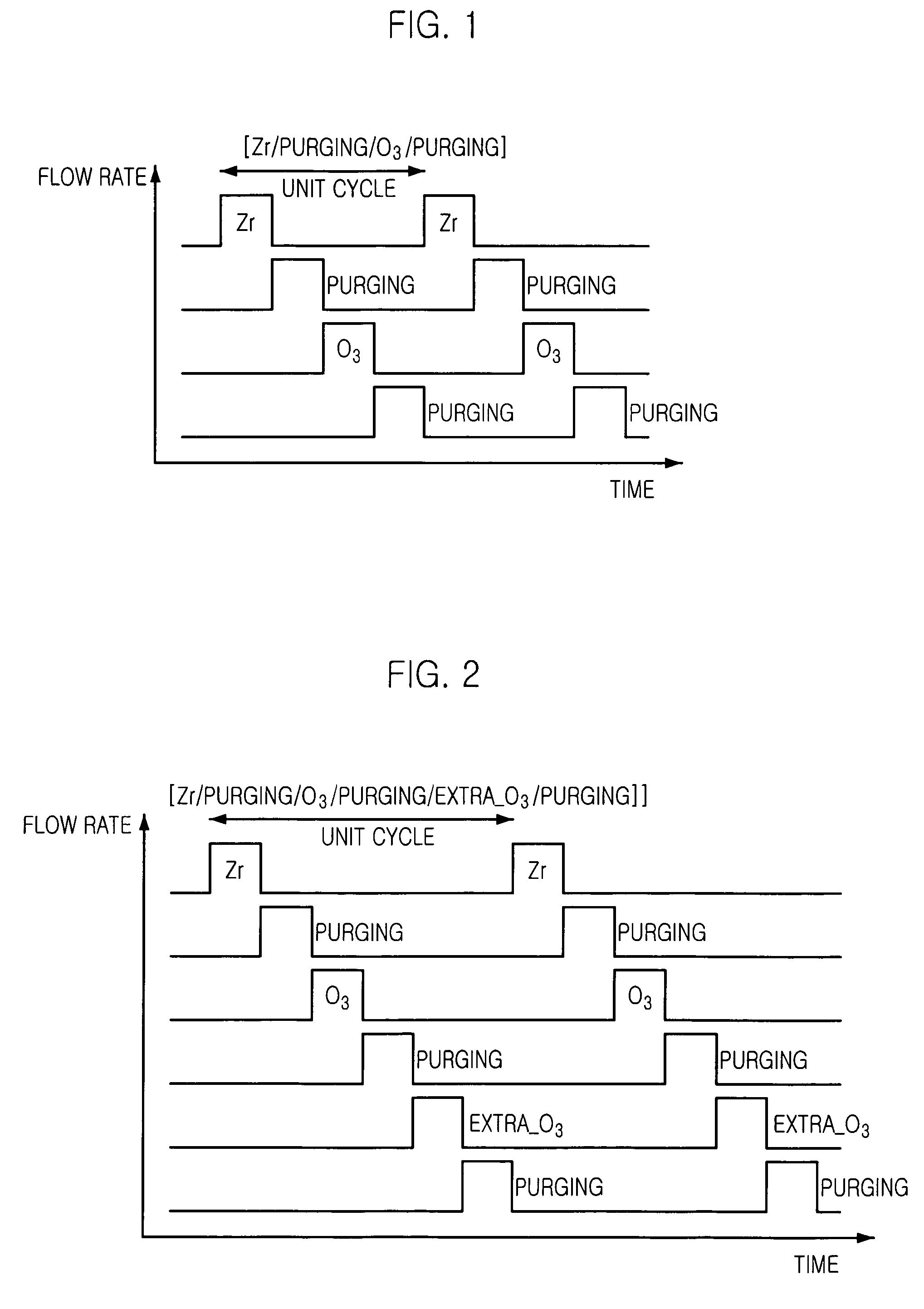
[0021]FIG. 1 is a graph illustrating a sequence of gas supply for forming a zirconium oxide (ZrO2) layer using an atomic layer deposition (ALD) method consistent with the present invention.

[0022]Consistent with the first embodiment of the present invention, a ZrO2 layer is deposited through an atomic layer deposition (ALD) method by repeating a unit cycle for forming an atomic layer of ZrO2, the unit cycle including supplying a zirconium (Zr) source, purging, supplying a reaction gas, and purging. The unit cycle is repeated until a thin film with a desirable thickness is obtained. That is, as for the unit cycle to deposit the ZrO2 layer, the Zr source is supplied and then, adsorbed into the surface of a substrate. Non-adsorbed parts of the Zr source remaining inside the chamber are purged out of the chamber. The reaction gas is supplied into the chamber and reacts with adsorbed parts of the Zr source. Through the above reaction of the reaction gas and the adsorbed parts of the Zr so...

second embodiment

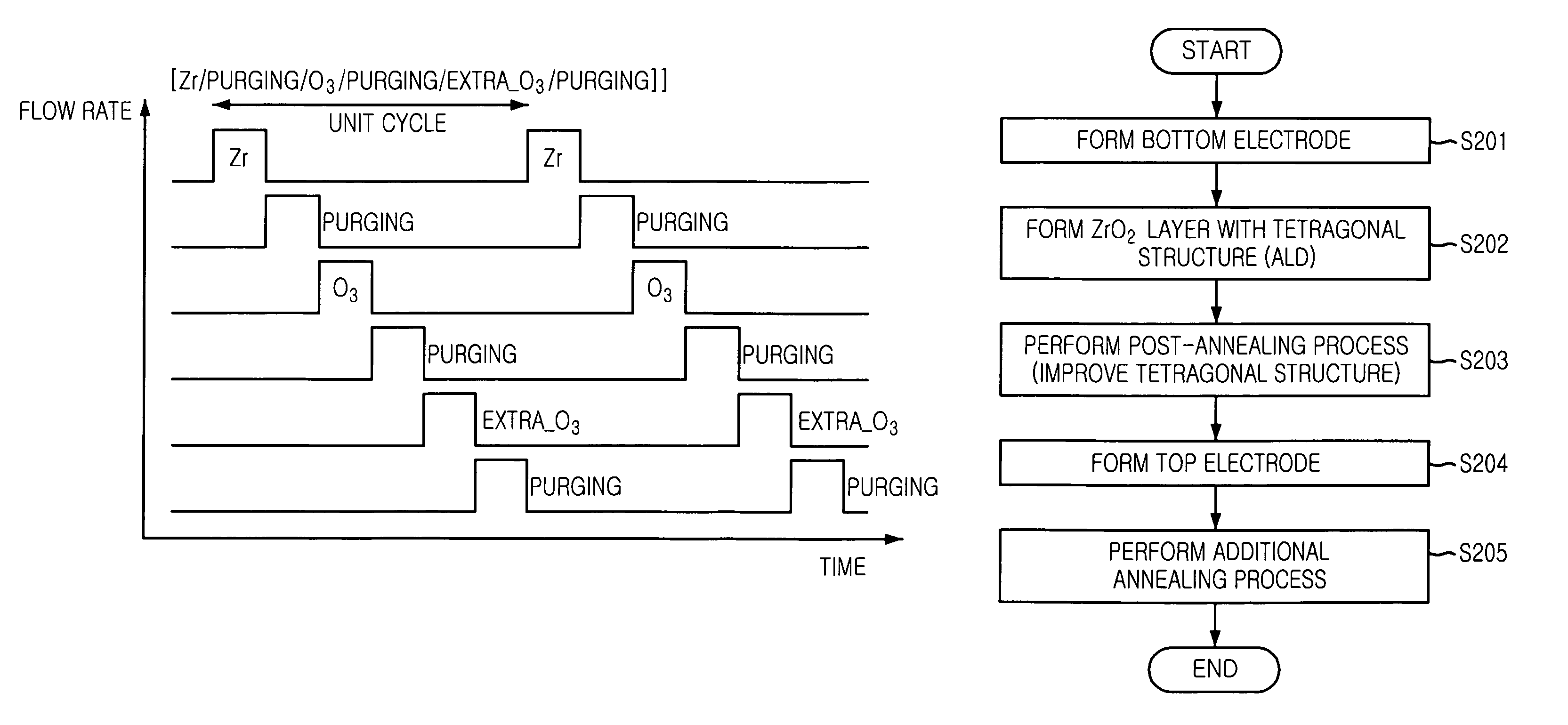
[0034]FIG. 2 is a graph illustrating a sequence of gas supply for forming a ZrO2 layer using an ALD method consistent with the present invention.

[0035]Compared to the unit cycle of the first embodiment of the present invention, a unit cycle consistent with the second embodiment of the present invention includes an additional step of supplying extra O3 gas denoted with ‘Extra_O3’ in FIG. 2 and an additional step of purging to improve tetragonality of a ZrO2 layer.

[0036]Accordingly, a unit cycle consistent with the second embodiment of the present invention includes supplying a Zr source, purging, supplying O3 gas, purging, supplying extra O3 gas, and purging, and may be denoted as [Zr / purging / O3 / purging / Extra_O3 / purging]. The extra O3 gas improves tetragonality of the ZrO2 layer.

[0037]During supplying the extra O3 gas, the O3 gas serves as a reaction gas and may be supplied with a flow rate ranging from approximately 0.1 slm to approximately 1 slm for a period ranging from approximat...


PUM

PropertyMeasurementUnit
temperatureaaaaaaaaaa
concentrationaaaaaaaaaa

Abstract

A method for forming a zirconium oxide (ZrO2) layer on a substrate in a chamber includes controlling a temperature of the substrate; and repeating a unit cycle of an atomic layer deposition (ALD) method. The unit cycle includes supplying a zirconium (Zr) source into a chamber, parts of the Zr source being adsorbed into a surface of the substrate; purging non-adsorbed parts of the Zr source remaining inside the chamber; supplying a reaction gas for reacting with the adsorbed parts of the Zr source; and purging non-reacted parts of the reaction gas remaining inside the chamber and reaction byproducts, wherein the temperature of the substrate and a concentration of the reaction gas are controlled such that the ZrO2 layer is formed with a tetragonal structure.

Description

RELATED APPLICATION[0001]The present application is based upon and claims the benefit of priority from Korean patent application No. KR 2006-0030665, filed in the Korean Patent Office on Apr. 4, 2006, the entire contents of which are incorporated herein by reference.TECHNICAL FIELD[0002]The present invention relates to a method for fabricating a semiconductor device; and more particularly, to a method for forming a zirconium oxide (ZrO2) layer and a method for fabricating a capacitor having the same.DESCRIPTION OF RELATED ARTS[0003]Recently, there has been an effort to apply a zirconium oxide (ZrO2) layer as a dielectric layer of a capacitor for a dynamic random access memory (DRAM) device with a size less than approximately 60 nm. However, if the ZrO2 layer is formed at a temperature less than approximately 250° C. through an atomic layer deposition (ALD) method and then, subjected to a thermal treatment, the ZrO2 layer with a monoclinic structure or a cubic structure having a low ...

Claims


Application Information

Patent Timeline
Patent Type & Authority Patents(United States)
IPC IPC(8): H01L21/469H01L21/31H10B12/00
CPCC23C16/405C23C16/45527H01L21/3141H01L21/31641H01L28/40Y02T50/67H01L21/02189H01L21/0228H01L21/02181H01L21/205H01L27/04H10B99/00H10B12/00H01L21/02337Y02T50/60
Inventor KIL, DEOK-SINSONG, HAN-SANGYEOM, SEUNG-JINPARK, KI-SEONROH, JAE-SUNGKIM, JIN-HYOCK
Owner SK HYNIX INC
Learn More