Multi-channel semiconductor integrated circuit
a semiconductor and integrated circuit technology, applied in the direction of pulse automatic control, oscillator generator, pulse technique, etc., can solve the problems of device breaking and chip area increasing, and achieve the effect of suppressing chip area increase and preventing device breaking
- Summary
- Abstract
- Description
- Claims
- Application Information
AI Technical Summary
Benefits of technology
Problems solved by technology
Method used
Image
Examples
first embodiment
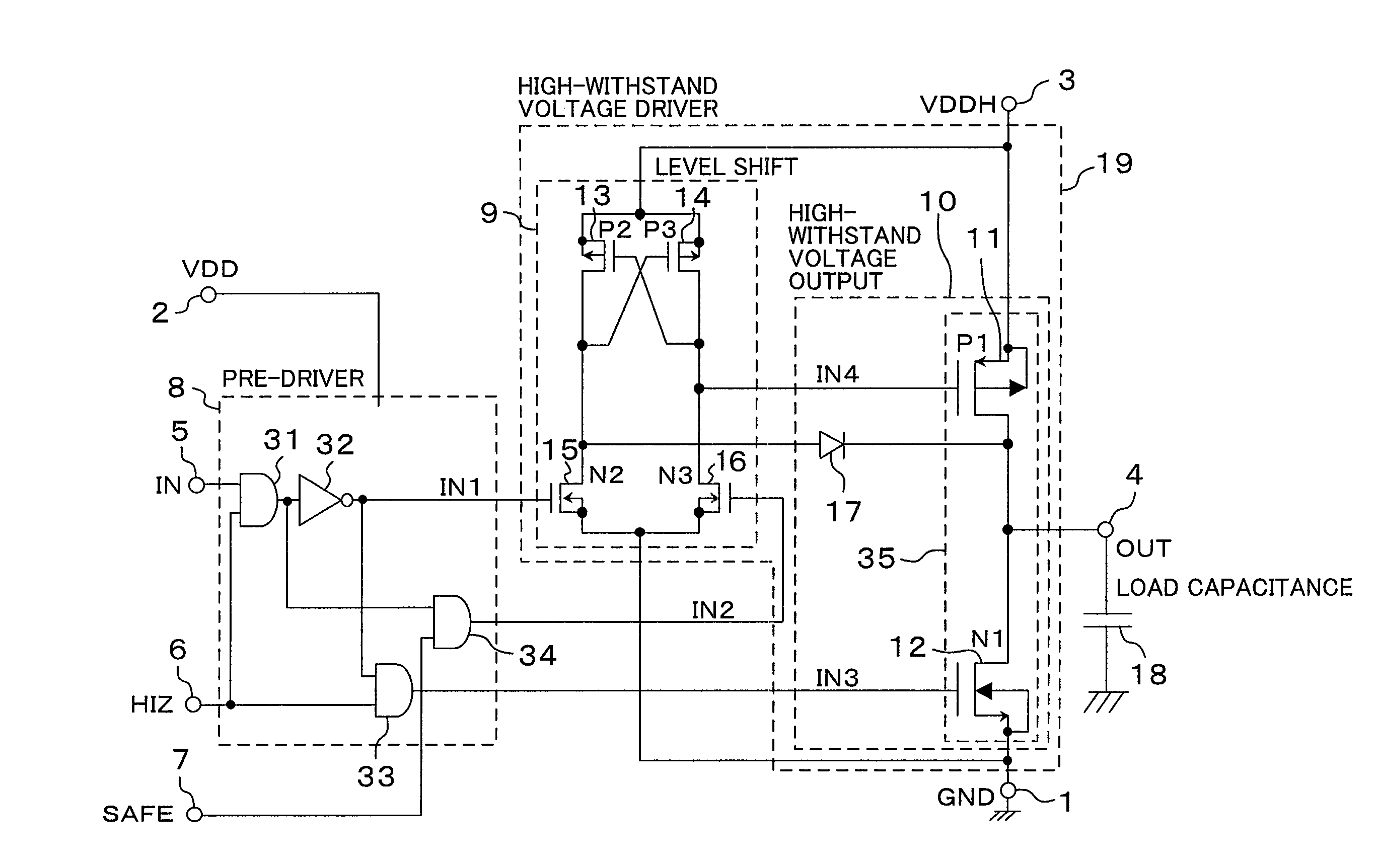
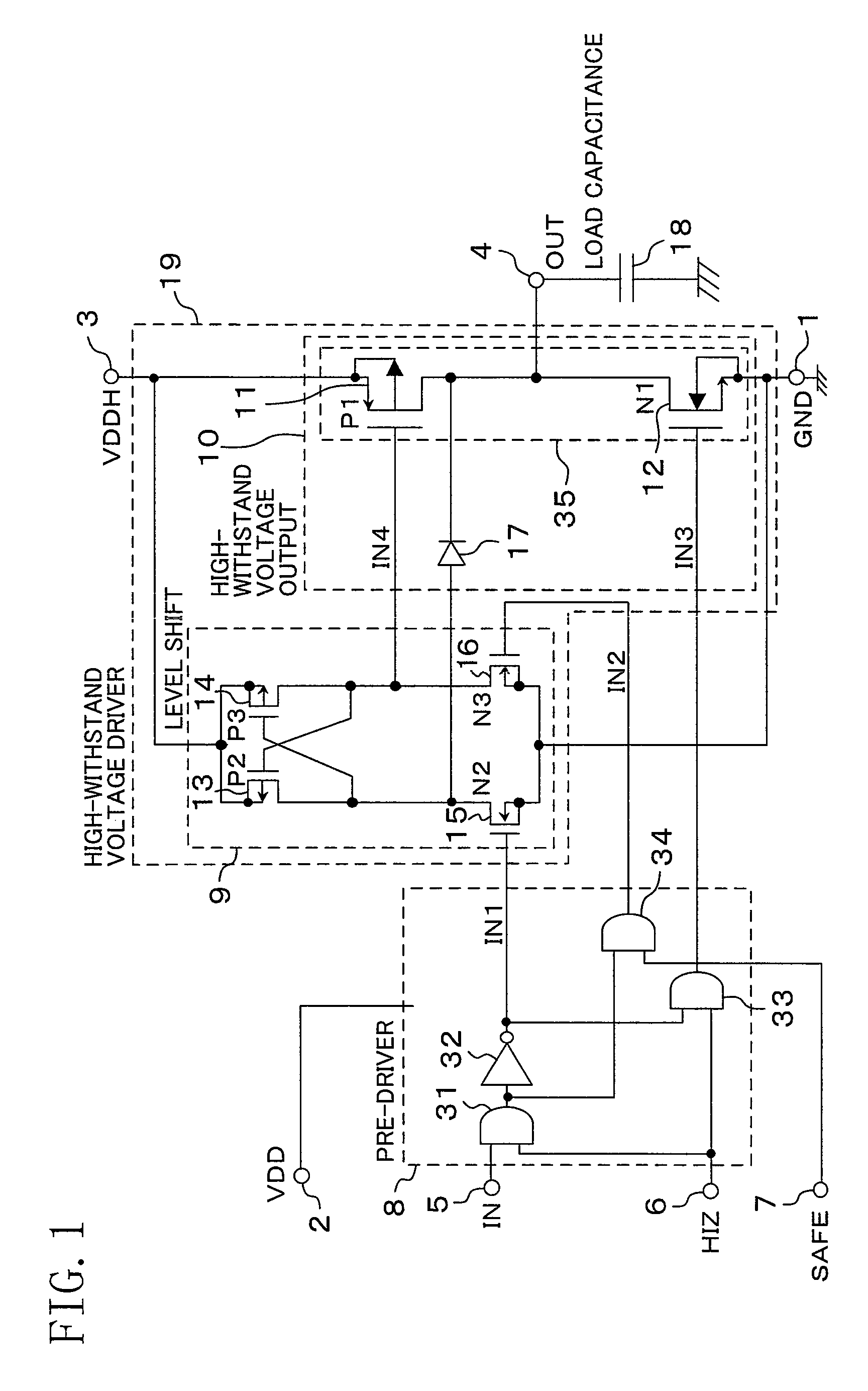
[0038]FIG. 1 is a diagram showing a configuration of a multi-channel semiconductor integrated circuit according to a first embodiment of the present invention.
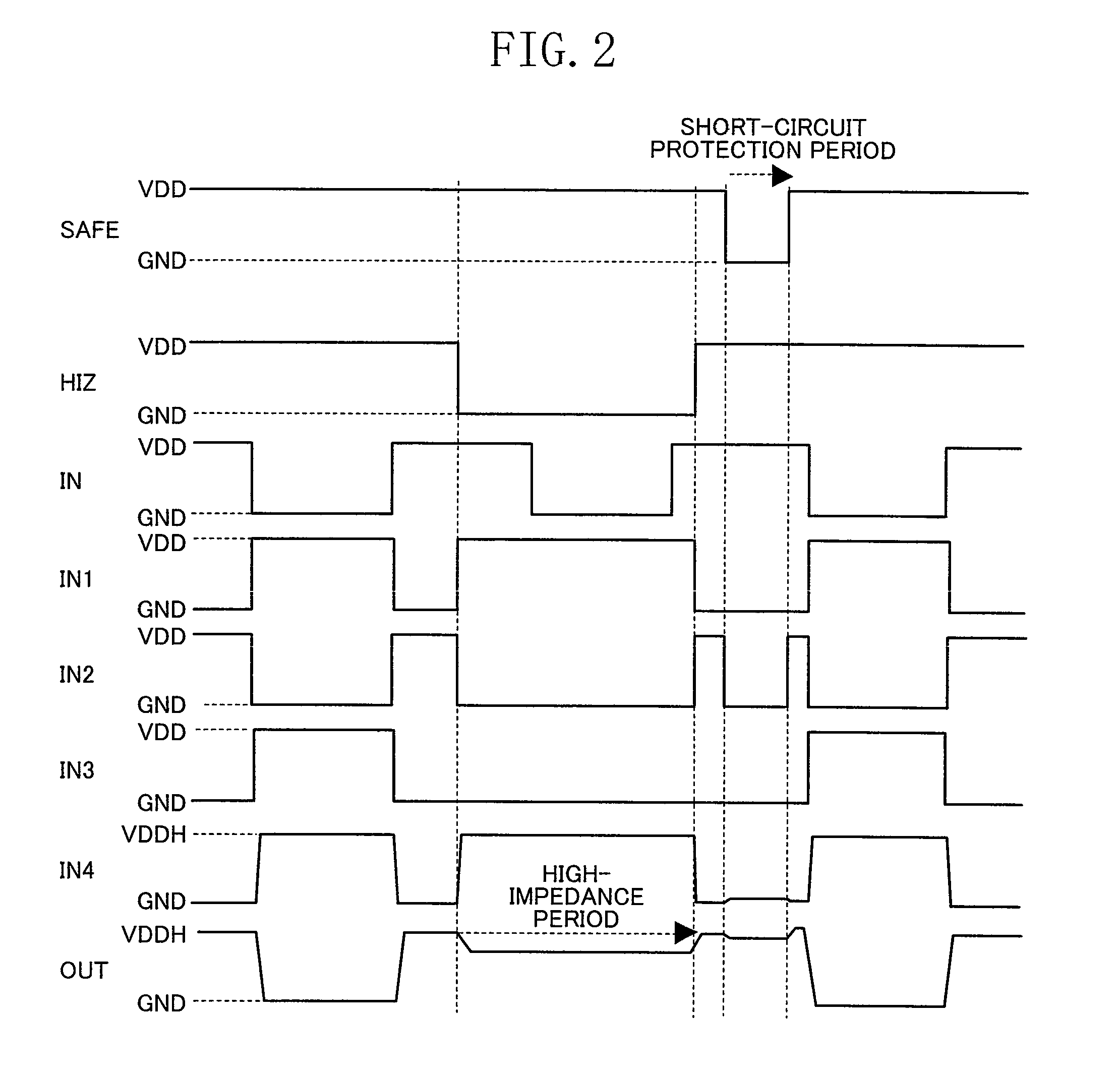
[0039]As shown in FIG. 1, a high-withstand voltage driver 19 comprises a high-withstand voltage output 10 and a level shift circuit 9. The high-withstand voltage output 10 has a half-bridge 35 including a high-side transistor 11 and a low-side transistor 12. The level shift circuit 9 includes thick-film gate P-type MOS transistors 13 and 14 and thin-film gate N-type MOS transistors 15 and 16. The high-withstand voltage driver 19 is driven by a pre-driver 8 in accordance with a signal which is input through a control input terminal 5 from a low-withstand voltage control section, to charge and discharge a load capacity 18. The high-side transistor 11 and the low-side transistor 12 are forced to be switched OFF, via the pre-driver 8 and the level shift circuit 9, in accordance with a signal which is input through a control input ...
second embodiment
[0053]FIG. 3 is a diagram showing a configuration of a multi-channel semiconductor integrated circuit according to a second embodiment of the present invention.
[0054]As shown in FIG. 3, by incorporating an oscillator 38 as an output protection circuit 20 into the multi-channel semiconductor integrated circuit, an input signal SAFE can be asynchronously input. When the parasitic capacitance is discharged over time, so that the H level cannot be held, or a short-circuit occurs, the state of the high-withstand voltage driver 19 can be reset. Note that an input signal OCR which is input through a terminal 23 is a control signal for the oscillator. The configuration of the built-in oscillator of FIG. 3 is only for illustrative purposes, and the present invention is not limited to this.
third embodiment
[0055]FIG. 4 is a diagram showing a configuration of a multi-channel semiconductor integrated circuit according to a third embodiment of the present invention.
[0056]As shown in FIG. 4, a high-withstand voltage driver 19 comprises a high-withstand voltage output 10 and a level shift circuit 9. The high-withstand voltage output 10 has a half-bridge 35 including a high-side transistor 11 and a low-side transistor 12. The level shift circuit 9 includes thick-film gate P-type MOS transistors 13 and 14 and thin-film gate N-type MOS transistors 15 and 16. The high-withstand voltage driver 19 is driven by a pre-driver 8 in accordance with a signal which is input through a control input terminal 5 from a low-withstand voltage control section, to charge and discharge a load capacity 18. The high-side transistor 11 and the low-side transistor 12 are forced to be switched OFF, via the pre-driver 8 and the level shift circuit 9, in accordance with a signal which is input through a control input ...
PUM
 Abstract
Description
Claims
Application Information
 - R&D
- Intellectual Property
- Life Sciences
- Materials
- Tech Scout
- Unparalleled Data Quality
- Higher Quality Content
- 60% Fewer Hallucinations
Browse by: Latest US Patents, China's latest patents, Technical Efficacy Thesaurus, Application Domain, Technology Topic, Popular Technical Reports.
© 2025 PatSnap. All rights reserved.Legal|Privacy policy|Modern Slavery Act Transparency Statement|Sitemap|About US| Contact US: help@patsnap.com


