
Shock-resistant packing box

A packaging box, impact-resistant technology, applied in packaging, transportation and packaging, rigid containers, etc., can solve the problems of reduced equipment stability, reduced vertical stiffness, reduced stability, etc., to achieve superior buffer performance and avoid equipment damage. , easy-to-use effects

Inactive Publication Date: 2013-09-11
WUXI HONGYUAN DEVFLEX
View PDF5 Cites 5 Cited by
  • Summary
  • Abstract
  • Description
  • Claims
  • Application Information

AI Technical Summary

Problems solved by technology

[0005] Under the same environmental conditions, the vibration isolation effect depends on the stiffness of the entire vibration isolation system. The smaller the stiffness, that is, the softer the vibration isolator, the more significant the vibration isolation effect, but too small stiffness will reduce the stability of the equipment under impact from different directions
The different stiffness of the wire rope vibration isolator in different loading directions (such as vertical, 45-degree inclination, lateral shear, etc.) leads to different vibration isolation performance in each direction of the vibration isolator. When the vibration isolator is loaded vertically, the vertical The stiffness is the largest, and the horizontal stiffness is the smallest. If the best vibration isolation effect is required at this time, then the vertical stiffness must be reduced as much as possible. At this time, when the center of gravity of the equipment is too high or vibration or impact occurs in the horizontal direction, it will cause the equipment to be damaged. shaking, reduced stability

Method used


Image

  • Shock-resistant packing box
  • Shock-resistant packing box

Examples


Embodiment Construction

[0012] The present invention will be further described below in conjunction with specific drawings.

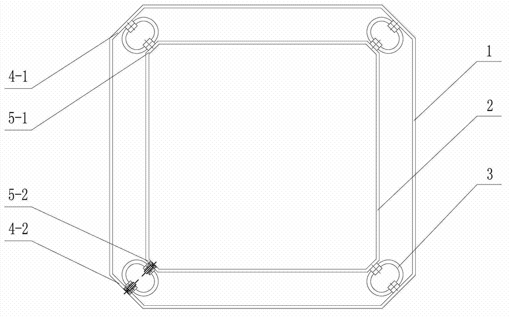
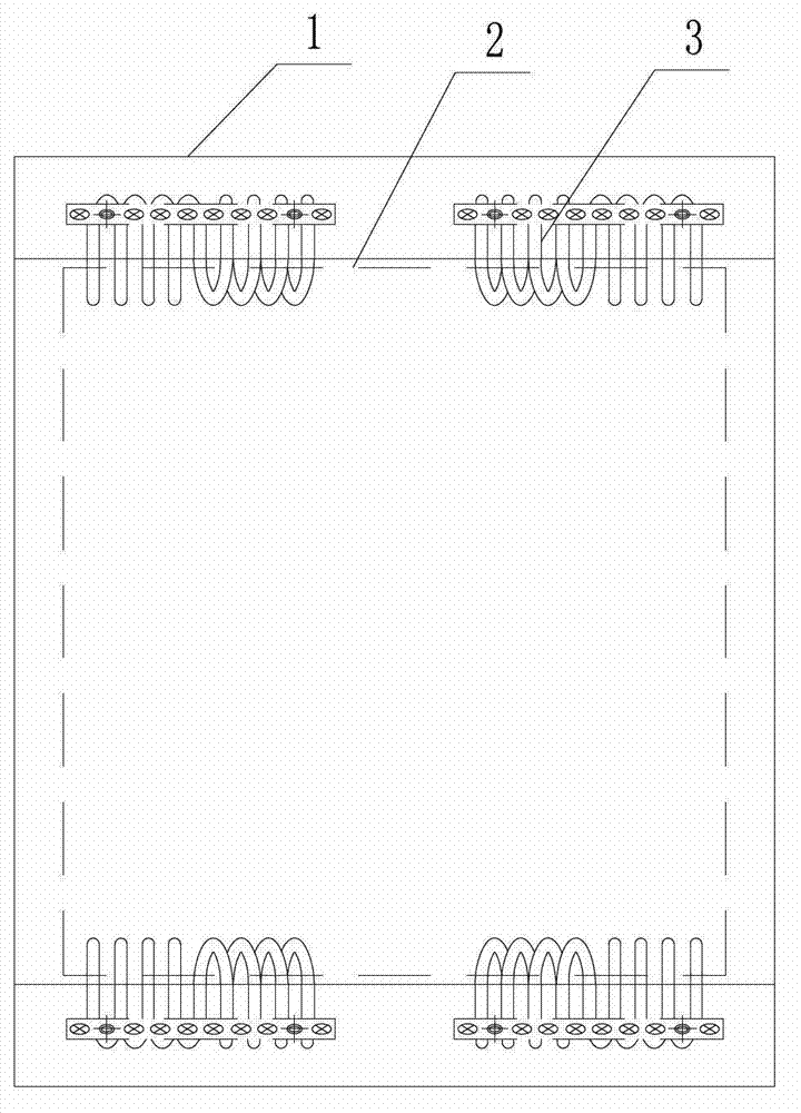
[0013] Such as Figure 1 ~ Figure 2 As shown: the impact-resistant packing box includes an outer box 1, an inner box 2, a wire rope vibration isolator 3, a first outer mounting surface 4-1, a second outer mounting surface 4-2, and a first inner mounting surface 5-1 , The second inner mounting surface 5-2, etc.

[0014] Such as figure 1 , figure 2 As shown, the present invention includes an outer box 1 and an inner box 2, two parallel sides on the top of the outer box 1 are provided with chamfers to form the first outer mounting surface 4-1, and two parallel sides at the bottom of the outer box 1 are provided with chamfers The second outer mounting surface 4-2 is formed, and the first outer mounting surface 4-1 and the second outer mounting surface 4-2 are symmetrically arranged; on the upper part of the inner box 2, two parallel to the first outer mounting surface 4-1 Cha...


PUM


Abstract

The invention relates to a shock-resistant packing box which comprises an outer box and an inner box. Chamfers are arranged on two parallel sides on the upper portion of the outer box to form a first outer installation face, chamfers are arranged on two parallel sides on the lower portion of the outer box to form a second outer installation face, and the first outer installation face and the second outer installation face are arranged symmetrically. Chamfers are arranged on two sides on the upper portion of the inner box and parallel to the first outer installation face to form a first inner installation face, chamfers are arranged on two sides on the lower portion of the inner box and parallel to the second outer installation face to form a second inner installation face, and steel wire rope vibration isolators are connected between the first outer installation face and the first inner installation face and between the second outer installation face and the second inner installation face. The shock-resistant packing box is used for conducting impact protection in the device transportation process, and damage to devices in the box due to the fact that the box falls accidentally can be avoided.

Description

technical field [0001] The invention relates to an impact-resistant packaging box, in particular to a protective packaging box used for object transportation, and belongs to the technical field of product packaging protection. Background technique [0002] At present, with the development of science and technology, more and more precision equipment and optical equipment need to be transported by logistics. These precision equipment are often unable to withstand excessive impact. When falling during transportation, especially during container transportation, it is inevitable that the phenomenon of falling will occur, which will cause damage to the equipment. [0003] The two technologies currently applied to equipment protection are: (1) to protect the equipment by adding buffer devices to the equipment; (2) to protect the equipment by improving the vibration isolation and anti-shock effect of the vehicle body by modifying the vehicle body. Method 1 needs to increase the cos...

Claims


Application Information

Patent Timeline
IPC IPC(8): B65D25/26B65D6/10B65D6/32F16F15/02
Inventor 胡存慧杨勇
Owner WUXI HONGYUAN DEVFLEX
Learn More