Resist pattern processing equipment and resist pattern processing method

a technology of resist pattern and processing equipment, which is applied in the field of resist pattern processing equipment and resist pattern processing methods, can solve the problems of ozone concentration being uneven on the surface, unable to obtain photoresist having a uniform linewidth, and the distance between the uv lamp and the stage in the surroundings of the substrate is much greater than the distance between the uv lamp and the substrate, etc., to achieve the effect of restrainting ozone and restrainting ozon

Inactive Publication Date: 2010-07-13
TDK CORPARATION
View PDF7 Cites 0 Cited by
  • Summary
  • Abstract
  • Description
  • Claims
  • Application Information

AI Technical Summary

Benefits of technology

[0007]As a resist removing apparatus, one using an oxygen plasma produced by a high-frequency wave such as a microwave at a frequency of about 2.45 GHz or a radiofrequency (RF) wave at a frequency of about 13.65 kHz has also been known. However, the resist removing apparatus using an oxygen plasma has been problematic in that it is unsuitable for regulating the linewidth of resist patterns on the order of nanometers, since a large amount of photoresist is removed at the time of plasma ignition. Though a shutter device may be added to the resist removing apparatus in order to avoid this problem, this makes the resist removing apparatus complicated and bulky, thus failing to regulate the linewidth of resist patterns easily at low cost.
[0023]The present invention can provide a resist pattern processing apparatus and resist pattern processing method which can achieve uniform and high-precision slimming of the linewidth of resist patterns arranged on a substrate in an inexpensive and easy manner.

Problems solved by technology

In the conventional resist removing apparatus such as the one mentioned above, however, nothing but the substrate is mounted on the stage, so that the distance between the UV lamp and the stage in the surroundings of the substrate is much greater than the distance between the UV lamp and the substrate.
As a result, the ozone concentration tends to become uneven in the surface of the substrate mounted on the stage in the conventional resist removing apparatus.
Hence, when the conventional resist removing apparatus is used for slimming the linewidth of the resist pattern on the substrate surface, the linewidth of the resist pattern may vary depending on the ozone concentration distribution in the substrate surface, whereby a photoresist having a resist pattern with a uniform linewidth cannot be obtained.
However, the resist removing apparatus using an oxygen plasma has been problematic in that it is unsuitable for regulating the linewidth of resist patterns on the order of nanometers, since a large amount of photoresist is removed at the time of plasma ignition.
Though a shutter device may be added to the resist removing apparatus in order to avoid this problem, this makes the resist removing apparatus complicated and bulky, thus failing to regulate the linewidth of resist patterns easily at low cost.

Method used


Image

  • Resist pattern processing equipment and resist pattern processing method
  • Resist pattern processing equipment and resist pattern processing method
  • Resist pattern processing equipment and resist pattern processing method

Examples


example 1

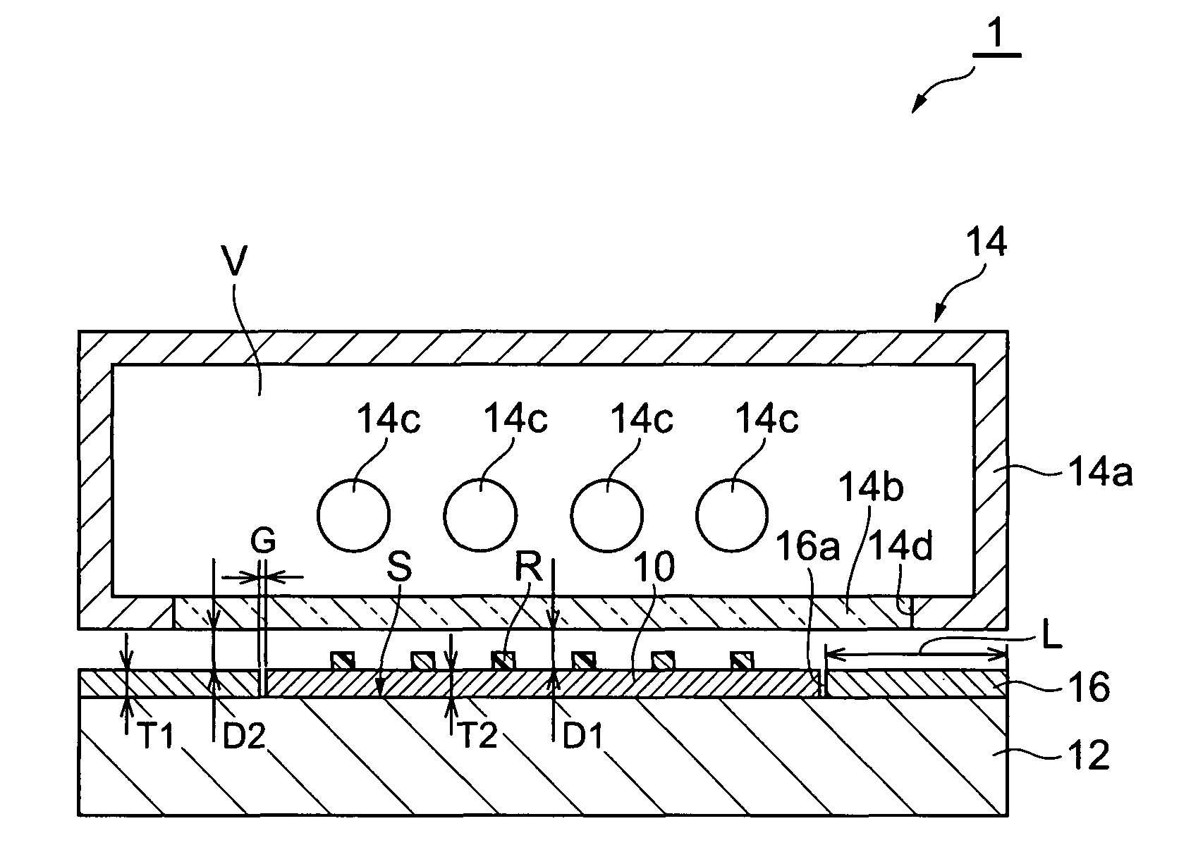
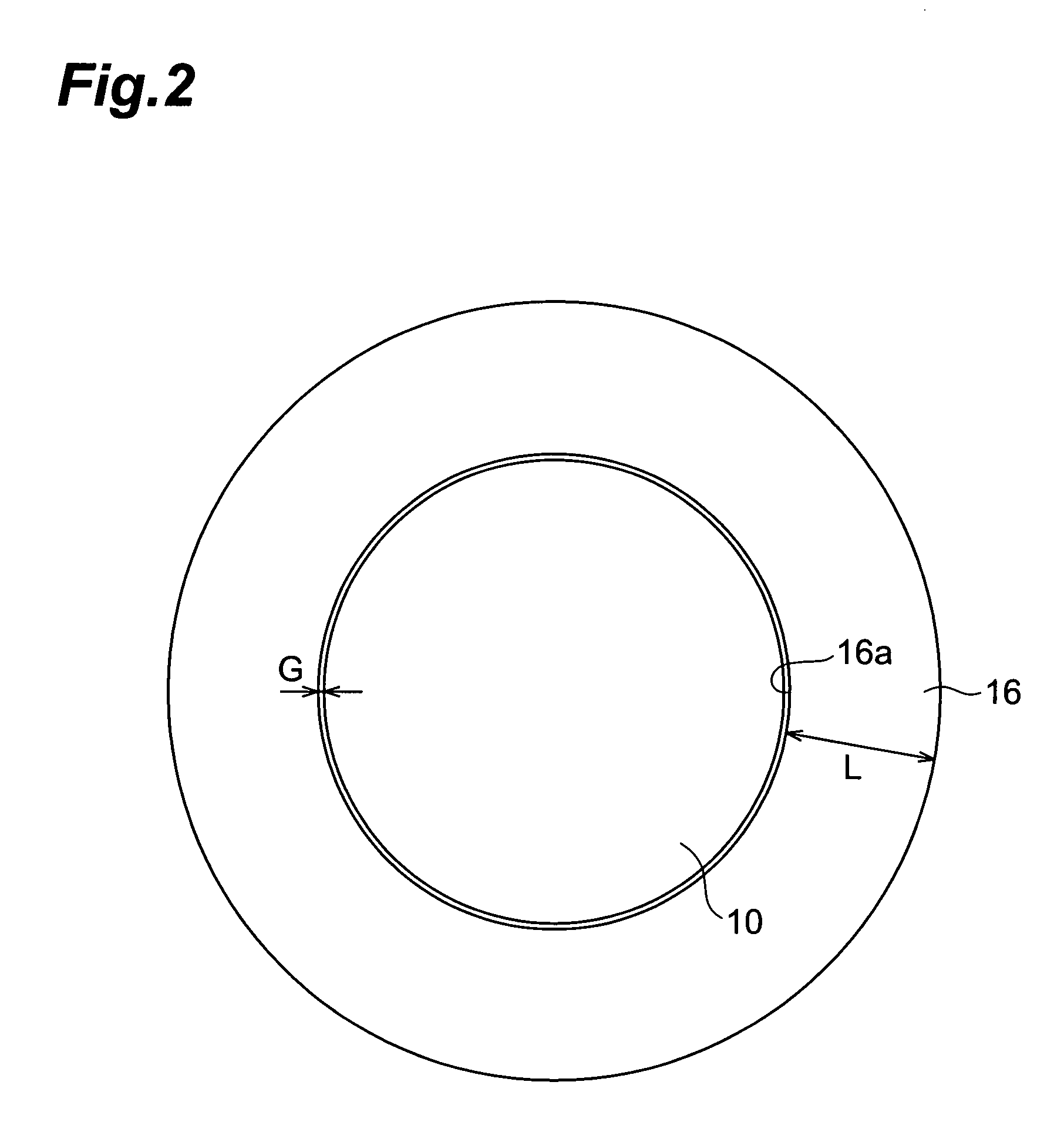
[0048]In Example 1, using the resist pattern processing apparatus 1 equipped with the annular member 16 surrounding the whole periphery of the substrate 10 as shown in FIG. 1 and FIG. 2, the photoresist R on the substrate 10 was irradiated for 3 minutes with UV rays by the UV lamps 14c, so as to slim the linewidth of a resist pattern. Here, used as the substrate 10 was one having a diameter of 6 inches, the distance D1 between the lower face of the glass plate 14b of the UV-emitting part 14 and the surface of the substrate 10 and the distance D2 between the lower face of the glass plate 14b of the UV-emitting part 14 in the surroundings of the substrate 10 and the surface of the annular member 16 were each set to 2 mm, the distance G between the side face of the substrate 10 and the inner peripheral face of the opening 16a of the annular member 16 was set to 1 mm, the thickness T1 of the annular member 16 and the thickness T2 of the substrate 10 were each set to 2 mm, the width L of...


PUM

PropertyMeasurementUnit
widthaaaaaaaaaa
distanceaaaaaaaaaa
frequencyaaaaaaaaaa

Abstract

A resist pattern processing apparatus comprises a stage for mounting a substrate having a patterned photoresist arranged on a surface thereof, a UV-emitting part for emitting UV rays to the stage, and an annular member for surrounding the whole periphery of the substrate. This allows the annular member to restrain ozone supplied near a mounting surface for the substrate on the stage from diffusing to the periphery of the stage, whereby the ozone concentration becomes even in the surface of the substrate mounted on the stage.

Description

BACKGROUND OF THE INVENTION[0001]1. Field of the Invention[0002]The present invention relates to a resist pattern processing equipment and a resist pattern processing method.[0003]2. Related Background Art[0004]A resist removing apparatus (ashing apparatus) has conventionally been known (see, for example, Japanese Patent Application Laid-Open No. 6-231735), which comprises a stage for mounting a substrate having a photoresist arranged on a surface and a UV lamp for emitting UV rays to the stage, and supplies ozone (O3) generated when the UV rays emitted from the UV lamp react with oxygen (O2) in the atmosphere to the vicinity of the substrate mounting surface in the stage.SUMMARY OF THE INVENTION[0005]For superfine processing of substrates, it has recently been demanded to regulate the linewidth of photoresist with a high precision in the order of nanometers. For fulfilling this demand, a technique for slimming the linewidth of a photoresist patterned on a substrate (resist pattern)...

Claims


Application Information

Patent Timeline
Patent Type & Authority Patents(United States)
IPC IPC(8): B08B7/00H01L21/302
CPCH01L21/0273H01L21/67115G03F7/42Y10S438/906
Inventor HATATE, HITOSHIKAMIJIMA, AKIFUMI
Owner TDK CORPARATION
Why Eureka
Try Eureka