Centrally gated cast metal rotary friction plates and method of manufacture

Inactive Publication Date: 2010-07-13
ROCHESTER WILLIAM R
View PDF11 Cites 13 Cited by
  • Summary
  • Abstract
  • Description
  • Claims
  • Application Information

AI Technical Summary

Benefits of technology

[0008]To eliminate this problem I have considered the gating (filling) system, the casting cavity and the mold immediately surrounding this molten metal as one mass of heat by the time the mold is poured. This was the basis for a design of a gating system to develop one natural, centralized thermal gradient from highest temperature at center of the mass to lower temperature around perimeter of mass for directional solidification from relatively cool perimeter back to hottest mass at center. This design fills the mold cavity in a horizontal position working with gravity to flow evenly throughout the cavity from the inside outward while maintaining a low profile for low head pressure to minimize potential mold wall movement which lends to a balance problem. Controlling the flow of the metal in the mold during the pour in order to provide a generally even fill and generally balanced temperature of the metal through appropriate orientation, gating and coring of the mold sets up the ability to control the solidification of the material from the outer perimeter inward to develop the desired uniform properties of the casting. This is particularly beneficial for brake rotor applications, where a uniform microstructure in the radial and circumferential direction on the friction faces of the rotor plates produces a corresponding uniform braking behavior when engaged by the brake pads to greatly reduce or all together eliminate brake pulsing and / or chatter otherwise caused by uneven wear of the friction faces due to hard and soft regions of the friction plates resulting from conventional casting techniques.
[0011]Some of the advantages of the present invention include the ability to control the flow of metal so that the velocity of the molten metal is dramatically reduced from that of the initial pour as it enters the friction plate regions of the cavity. Also, the shortest flow distance is employed by going across the top of the core and directly into the upper most friction plate region. The central fill controls heat dissipation as a thermal gradient develops from the heat source to the heat escape near the outer boundaries of the casting cavity. The centralized heat mass also serves as a source of molten metal to feed the surrounding cast features during solidification in order to make sound castings.
[0012]The secondary and primary distribution reservoirs have the advantage of receiving a steady stream of the hottest metal from the sprue throughout the pour, and are thus the last of the molten metal to solidify apart from the sprue. As such, the secondary reservoirs serve as a plurality of circumferentially spaced risers that continue to feed molten metal to the mold cavity as it solidifies from the outer perimeter inward to make a sound cast structure with uniform microstructure and properties.
[0013]Another advantage of the primary and secondary distribution reservoirs is that they serve to trap any dross in the molten metal stream before it enters the casting cavity. The wall of the primary distribution reservoir acts as a dam to hold back dross as the metal enters the secondary distribution reservoirs. The choked bottom inlet of the secondary distribution reservoirs act as weirs to trap any remaining dross before the metal enters the cavity into the upper friction plate forming region. As such, the metal of the final casting is very clean and generally free of impurities.
[0014]According to a further aspect of the invention, two or more brake rotors can be cast simultaneously in the mold by stacking the mold cavities vertically and with the central openings in the cores aligned and in open communication with the sprue at the top. As the metal is poured into the mold, the metal begins to fill the upper most mold cavity in the manner described above, but also a fraction of the stream travels through the central openings in the cores and simultaneously fills the lower mold cavities in the same manner. The size and shape of the openings in the cores can be varied to choke the flow from the sprue and thus control the rate of delivery of molten metal to the molds. In this way, multiple rotors can be cast in one mold, increasing efficiency and lowering the cost of making rotors.

Problems solved by technology

There are problems in automotive circles today of irregular friction reaction and vibration of rotary friction disc brake rotor and clutch plates that are a direct result from the way in which they are cast.
The relative soft and hard regions in the circumferential direction of a rotary friction plate cause irregular wear, strength and braking resistance over the life of the rotary friction element.
The most noticeable result in brake discs is an undesirable pulsing feel of the brakes as the operator of the vehicle slows the vehicle, rather than a smooth, even braking feel.
These thermal gradients during solidification cause uneven structure by areas.
Irregular temperatures from area to area promote differentials in solidification rates which promote differences in graphite flake size, grain size and hardness as well as variable strengths and stresses which can lead to distortion when relieved with heating and cooling of repeated function or come apart in the soft and relatively weak areas.
Several attempts have been made to modify present systems of casting and have improved the situation somewhat but have failed to eliminate the cast structure variation because they still use the vertical (on edge) orientation or widespread inlets and outside inward feeding around horizontal orientation.

Method used


Image

  • Centrally gated cast metal rotary friction plates and method of manufacture
  • Centrally gated cast metal rotary friction plates and method of manufacture
  • Centrally gated cast metal rotary friction plates and method of manufacture

Examples


Embodiment Construction

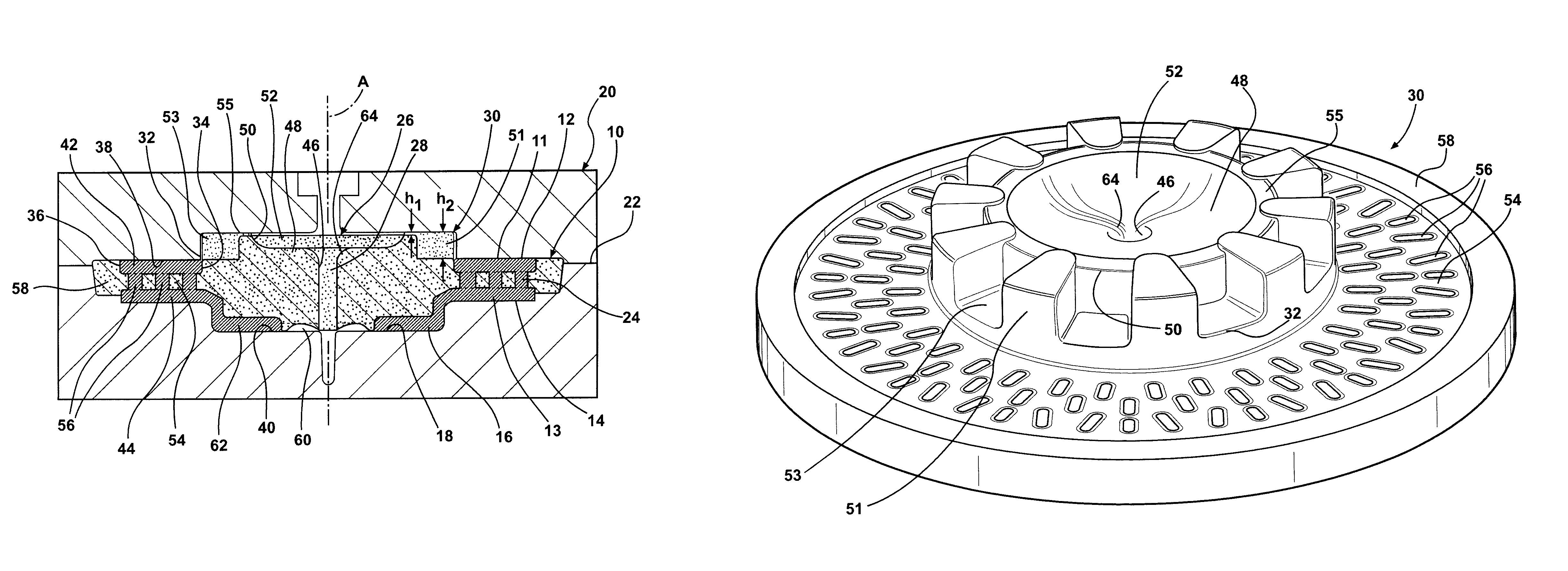
[0026]I have cast standard brake rotors and clutch plates using this central filling system through the open center of the casting, which routes the molten metal through the inside diameter, horizontally across the short feeding distance to the outside diameter. This produces no noticeable variation around the solid casting structure as the one thermal gradient solidified in one circular flow of heat extraction. This horizontal orientation can be adapted for vertically parted molds but it best suited for horizontally parted molds, and is adaptable to all rotary friction plates and other devices where uniform development of cast metal properties is desired in the circumferential direction across the friction surfaces.

[0027]The way I have done this is to use the horizontal orientation of the mold cavity but pour all the melt in through a central gating and outward through the cavity, (not from outside inward) of the volume to be cast, through several closely positioned inlets on the s...


PUM

PropertyMeasurementUnit
Heightaaaaaaaaaa
Distributionaaaaaaaaaa
Frictionaaaaaaaaaa

Abstract

A method of casting a rotary friction plate includes preparing a casting mold with a cavity and a core shaped to form the friction plate. Molten metal is poured into the mold through a central sprue where a portion of the metal flows radially outward across the top of the core to fill friction plate forming regions of the cavity from above, while another portion flows through a central opening in the core to fill a hub forming region at the bottom of the cavity as well as additionally supply metal to the lower friction plate forming region from below. The metal is allowed to cool, which begins at the radially outer regions of the at least one friction surface and progresses radially inward to develop a uniform cast structure.

Description

[0001]This application is a Continuation-in-Part and claims priority to U.S. Provisional Patent Application Ser. No. 60 / 649,407, filed Feb. 2, 2005 and U.S. patent application Ser. No. 11 / 345,814, filed Feb. 2, 2006 now abandoned, both which are incorporated herein by reference.BACKGROUND OF THE INVENTION[0002]1. Technical Field[0003]This invention relates generally to metal casting and more particularly to controlling heat flow and solidification during casting.[0004]2. Related Art[0005]There are problems in automotive circles today of irregular friction reaction and vibration of rotary friction disc brake rotor and clutch plates that are a direct result from the way in which they are cast. These components are typically cast in vertically split molds with the friction plate oriented vertically and filled through a bottom inlet gate so that the mold cavity is filled from the bottom up. Regardless of where the molten metal enters the vertical mold cavity, gravity causes the low side...

Claims


Application Information

Patent Timeline
IPC IPC(8): B22D33/04B22C9/10
CPCB22C9/10B22D15/005
Inventor ROCHESTER, WILLIAM R.
Owner ROCHESTER WILLIAM R
Why Eureka
Try Eureka