
Controlled pore size distribution porous ceramic honeycomb filter, honeycomb green body, batch mixture and manufacturing method therefor

a porous ceramic and filter technology, applied in the direction of metal/metal-oxide/metal-hydroxide catalysts, machines/engines, chemical/physical processes, etc., can solve the problems of low efficiency, high cost of sic, so as to reduce the pressure drop of wash-coated, reduce the risk of clogging of small pores, and reduce the effect of clogging

Active Publication Date: 2010-06-29
CORNING INC
View PDF36 Cites 24 Cited by
  • Summary
  • Abstract
  • Description
  • Claims
  • Application Information

AI Technical Summary

Benefits of technology

The solution effectively lowers wash-coated pressure increase and overall backpressure while maintaining good filtration efficiency and thermal shock resistance, achieving a porous ceramic honeycomb filter with reduced pressure drop and improved engine performance.

Problems solved by technology

However, diesel emissions have come under attack both in the United States and Europe, as being generally undesirable.
One of the biggest challenges in lowering diesel emissions is controlling the levels of particulates present in the diesel exhaust stream.
However, SiC is expensive, heavy and has a relatively high coefficient of thermal expansion (CTE).
Thus, the use of SiC materials in diesel particulate filters requires expensive multi-component designs (sometimes referred to as segmented designs) to overcome the material's high CTE.
As the layer of soot collects on the surfaces of the inlet channels of the particulate filter, the lower permeability of the soot layer causes a gradual rise in the back pressure of the filter against the engine (soot loaded back pressure), causing the engine to work harder.
Thus, it should be recognized that a significant problem associated with diesel particulate filters is backpressure.
Moreover, the coated pressure drop may exceed the uncoated pressure drop by a significant margin.

Method used


Image

  • Controlled pore size distribution porous ceramic honeycomb filter, honeycomb green body, batch mixture and manufacturing method therefor
  • Controlled pore size distribution porous ceramic honeycomb filter, honeycomb green body, batch mixture and manufacturing method therefor
  • Controlled pore size distribution porous ceramic honeycomb filter, honeycomb green body, batch mixture and manufacturing method therefor

Examples


examples

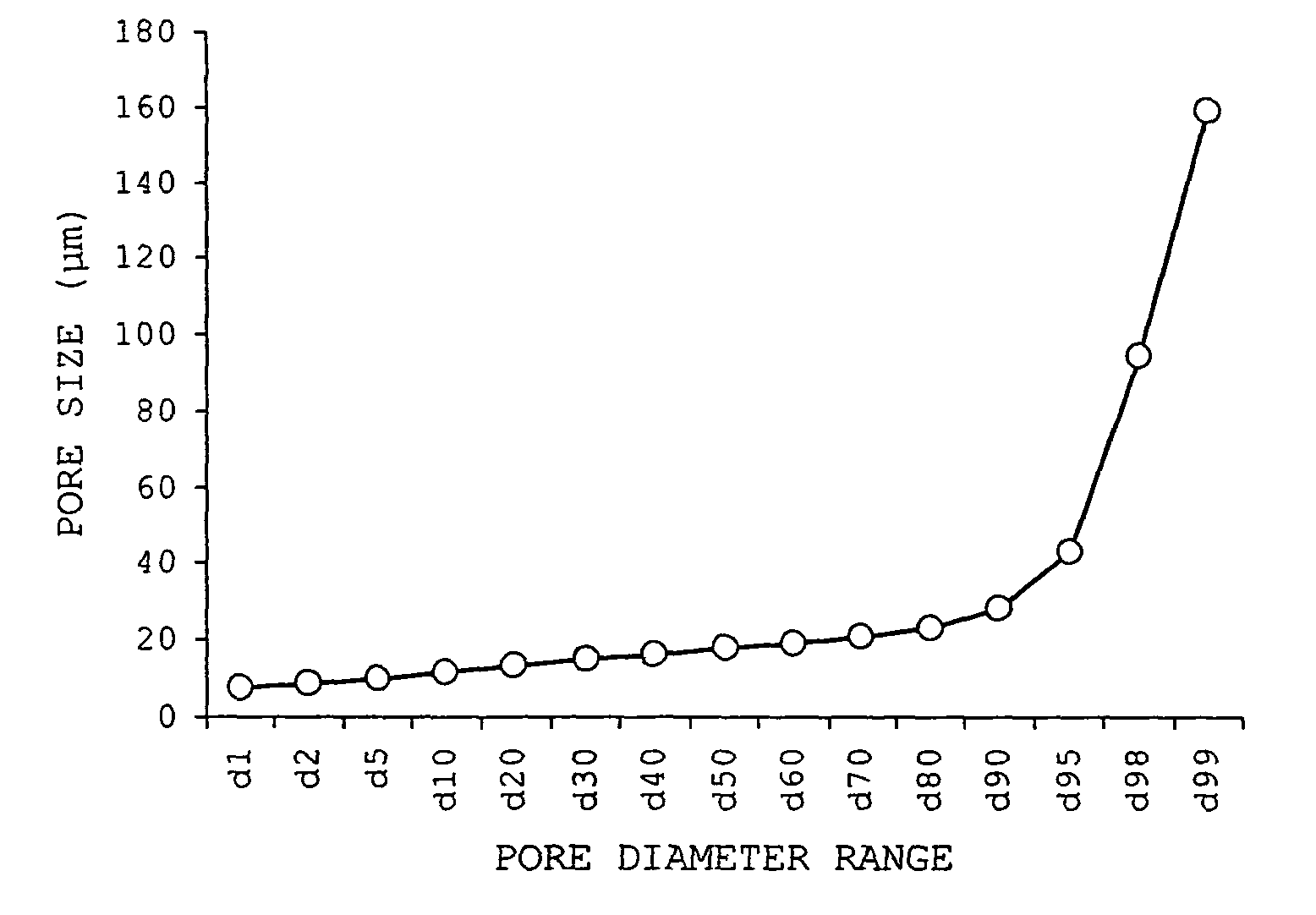
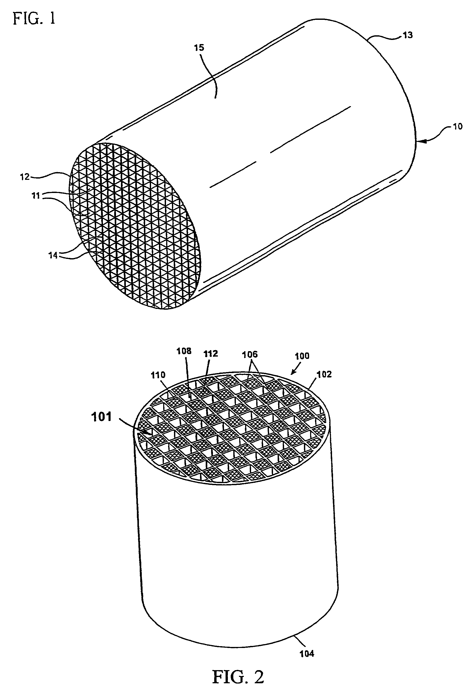
[0064]As shown in FIG. 1, inventive examples of cordierite green bodies 10 were prepared by weighing out the dry ingredients including various examples of the inventive pore formers listed in Table 2 and forming aids such as a cellulosic material, for example methyl cellulose, and sodium stearate. The dry ingredients are then mixed with a solvent vehicle, such as with water, and kneaded in a preferably stainless steel muller to form an extrudable plastic mass. The plastic mass is then formed, preferably extruded, into a green body, as described in U.S. Pat. No. 5,205,991, for example. Upon being extruded, the cellular honeycomb green bodies are cut to a log length.

[0065]The extruded green body 10 includes a honeycomb structure having a plurality of generally parallel cell channels 11 formed, at least partially defined by intersecting cell walls 14 (otherwise referred to as “webs”) that extend from a first end 12 to a second end 13. Preferably, the green body 10 also includes an extr...


PUM

PropertyMeasurementUnit
pore diameteraaaaaaaaaa

Abstract

A porous ceramic honeycomb filter manufactured from an oxide-based ceramic material having a pore size distribution with d1≧7.0 microns. Preferably, the oxide-based material is cordierite or aluminum titanate. Alternatively, the filter contains a cordierite-containing ceramic body with a narrow pore size distribution with db≦1.00, wherein db=(d90−d10) / d50. Also disclosed is a batch mixture, method and honeycomb green body made from mixture of inorganic source materials selected from the group of magnesia sources, alumina sources, and silica sources, and a pore former having a narrow particle size distribution with dps≦0.90, wherein dps={(dp90−dp10) / dp50}. The pore former is preferably selected from a group consisting of canna starch, sago palm starch, green mung bean starch, and single-mode potato starch.

Description

RELATED INVENTIONS[0001]The present invention claims the benefit of U.S. Provisional Application No. 60 / 741,355 filed Nov. 30, 2005 and entitled “Controlled Pore Size Distribution Porous Ceramic Honeycomb Filter, Honeycomb Green Body, Batch Mixture And Manufacturing Method Therefor.”FIELD OF THE INVENTION[0002]The present invention relates to a porous ceramic honeycomb article and honeycomb green body, batch mixture and method of manufacturing therefor. More particularly, the present invention relates to porous ceramic honeycomb filters exhibiting controlled pore size distribution and manufacture thereof.BACKGROUND OF THE INVENTION[0003]Recently much interest has been directed towards diesel engines due to their inherent fuel efficiency and durability. However, diesel emissions have come under attack both in the United States and Europe, as being generally undesirable. As such, stricter environmental regulations will require diesel engines to meet higher emissions standards. Therefo...

Claims


Application Information

Patent Timeline
Patent Type & Authority Patents(United States)
IPC IPC(8): B01D39/06B01D24/00B01D39/14B01D50/00F01N3/08F01N3/00F01N3/10
CPCB01D39/2068C04B38/0012C04B38/0006C04B35/478C04B35/195C04B38/0054C04B38/0074C04B38/0645B01D2239/10C04B2111/343C04B2111/2084C04B2111/0081C04B2111/00793C04B2111/00129
Inventor MIAO, WEIGUOSHUSTACK, PAUL JOHNSKOLNY, JENNIFER LYNNWANG, JIANGUOXIE, YUMING
Owner CORNING INC
Learn More