
DRAM power management in a memory controller

a memory controller and power management technology, applied in the direction of memory architecture accessing/allocation, instruments, sustainable buildings, etc., can solve the problems of heat management problems, particularly pronounced problems, and excessive power usag

Inactive Publication Date: 2010-06-15
INT BUSINESS MASCH CORP
View PDF5 Cites 22 Cited by
  • Summary
  • Abstract
  • Description
  • Claims
  • Application Information

AI Technical Summary

Problems solved by technology

Excess power usage is not only costly and inefficient, but also leads to heat management problems.
These problems are particularly pronounced in computer systems having large amounts of memory, such as server systems.
However, DRAM is much more power intensive.
DRAM can consume up to 45% of a system's overall power.
Unfortunately, the overuse of this mechanism can limit performance as there are associated entrance and exit latencies for a particular low power mode.
Since threshold values are system- and application-dependent, the algorithms are difficult to tune.
In cacheless single-processor systems, compile-time techniques can help the memory controller make better predictions for idle periods of memory sections, but in systems with multi-level caches or with shared memory controllers the role of the compiler for power savings is limited.
However, with the use of large page sizes, OS-based techniques which require data migration may degrade performance considerably.
Any approach that minimizes the number of active memory devices also reduces the available memory bandwidth which can adversely affect performance.
These approaches are not transparent to software and so can entail significant programming difficulties.
In a system where bank conflicts cause long delays, some commands in reorder queues may be blocked until conflicts related to those commands are resolved.
While memory schedulers that reorder commands can significantly improve performance, they are unfortunately at odds with memory schedulers that use power-down modes.

Method used


Image

  • DRAM power management in a memory controller
  • DRAM power management in a memory controller
  • DRAM power management in a memory controller

Examples


Embodiment Construction

)

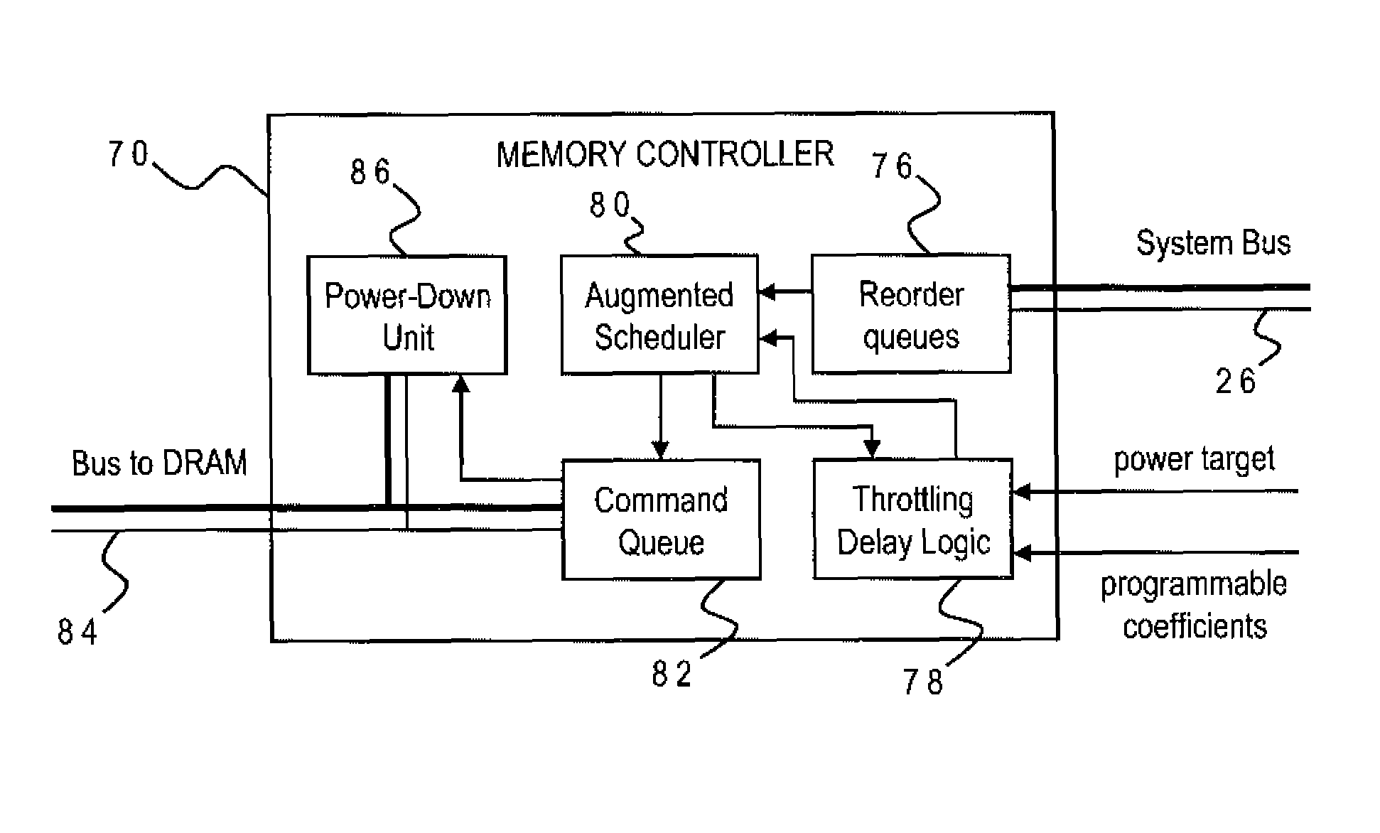
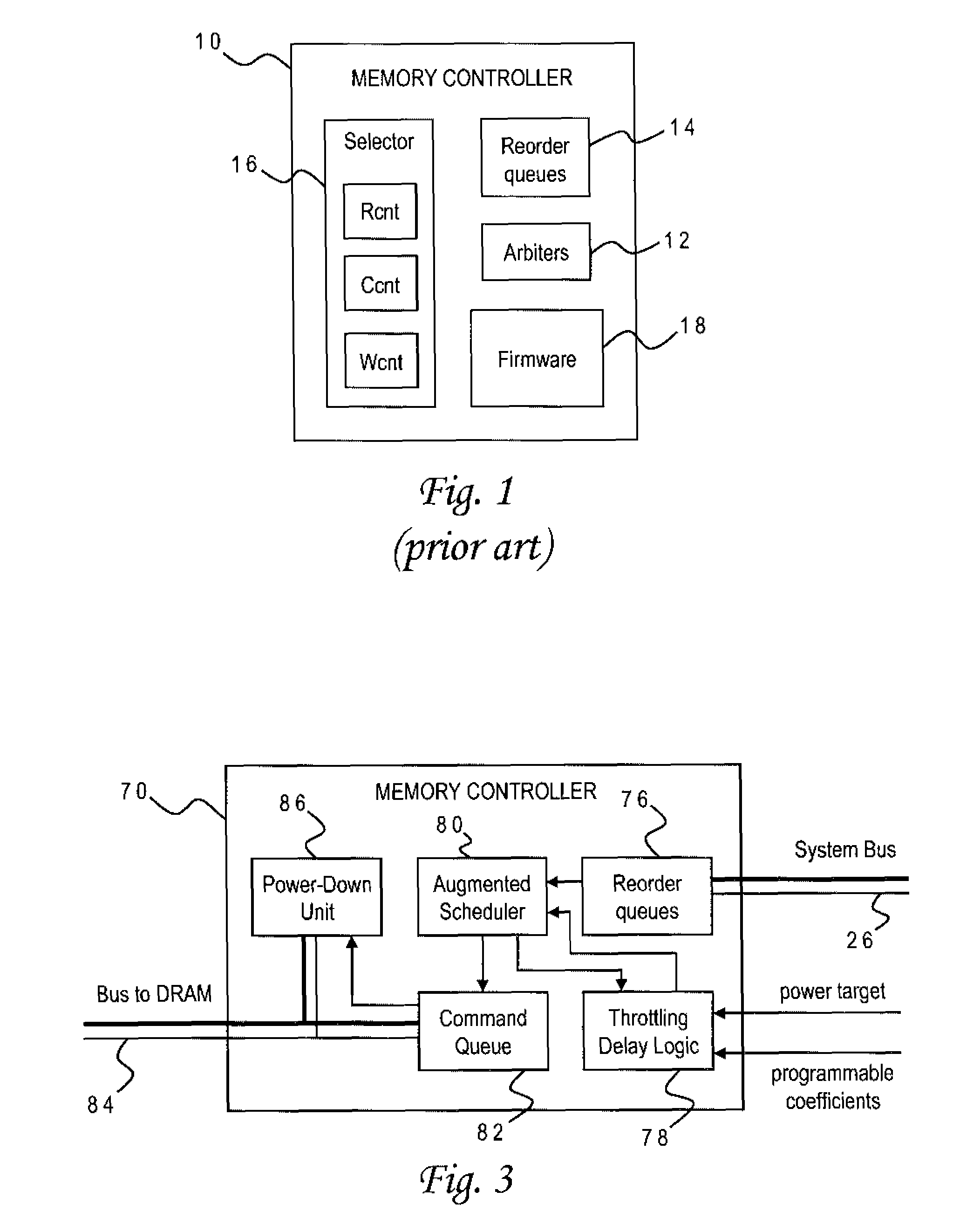
[0029]The present invention is directed to power management for memory subsystems of data processing systems, and is accordingly usable in a wide variety of such systems including general-purpose computers, distributed computing environments or special-purpose devices. The invention is applicable to memory arrays having various functions such as central (system) memory or local cache memory, and may be further implemented with any type of memory structure but is particularly advantageous for those memory technologies which require higher power consumption like DRAM and variations thereof such as synchronous DRAM (SDRAM).

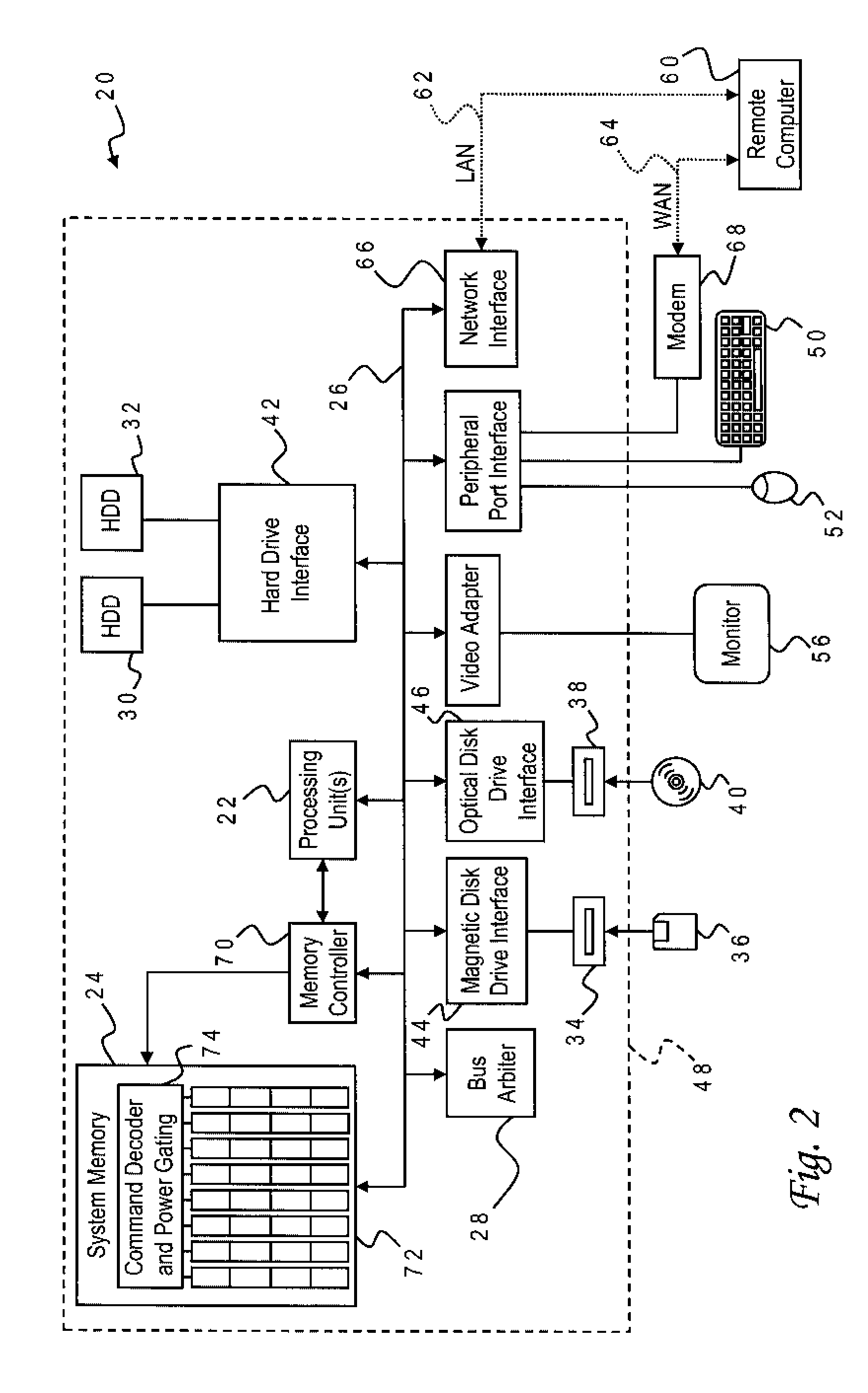
[0030]With reference now to the figures, and in particular with reference to FIG. 2, there is depicted one embodiment 20 of a computer system constructed in accordance with the present invention. Computer system 20 may for example be a server system adapted to provide computing services across a network such as the Internet. Computer system 20 is generally comprised...


PUM


Abstract

A memory controller uses a power- and performance-aware scheduler which reorders memory commands based on power priorities. Selected memory ranks of the memory device are then powered down based on rank localities of the reordered commands. The highest power priority may be given to memory commands having the same rank as the last command sent to the memory device. Any memory commands having the same power priority can be further sorted based on one or more performance criteria such as an expected latency of the memory commands and an expected ratio of read and write memory commands. To optimize the power-down function, the power-down command is only sent when the selected memory rank is currently idle, the selected memory rank is not already powered down, none of the reordered memory commands correspond to the selected rank, and a currently pending memory command cannot be issued in the current clock cycle.

Description

CROSS-REFERENCE TO RELATED APPLICATION[0001]This application is related to U.S. patent application Ser. No. 11 / 775,517 filed concurrently herewith on Jul. 10, 2007.BACKGROUND OF THE INVENTION[0002]1. Field of the Invention[0003]The present invention generally relates to power management in data processing systems, and more particularly to a method of controlling power usage of a memory structure such as dynamic, random-access memory (DRAM).[0004]2. Description of the Related Art[0005]Power usage has become a dominant concern in the development of data processing systems. Excess power usage is not only costly and inefficient, but also leads to heat management problems. These problems are particularly pronounced in computer systems having large amounts of memory, such as server systems. Servers typically use dynamic random-access memory (DRAM) which is preferable over other memory structures such as static random-access memory (SPAM) because DRAM is more dense. However, DRAM is much m...

Claims


Application Information

Patent Timeline
Patent Type & Authority Patents(United States)
IPC IPC(8): G11C5/14G06F12/00
CPCG06F1/3225G06F1/3275G06F1/3287G06F12/0215Y02B60/1228G06F2212/1028Y02B60/1225Y02B60/1282Y02D10/00
Inventor HUR, IBRAHIMLIN, CALVIN
Owner INT BUSINESS MASCH CORP
Learn More