Eureka AIR delivers breakthrough ideas for toughest innovation challenges, trusted by R&D personnel around the world.

Logical bridging system and method

a logical bridging and data packet technology, applied in the field of data communication, can solve the problems of limited service instances of architectures, conventional bridging hardware cannot extract rssi information tram data packets originating from wireless networks, etc., and achieve the effect of facilitating logical bridging functionality

Active Publication Date: 2008-09-18
MARVELL ISRAEL MISL
View PDF4 Cites 470 Cited by
  • Summary
  • Abstract
  • Description
  • Claims
  • Application Information

AI Technical Summary

Benefits of technology

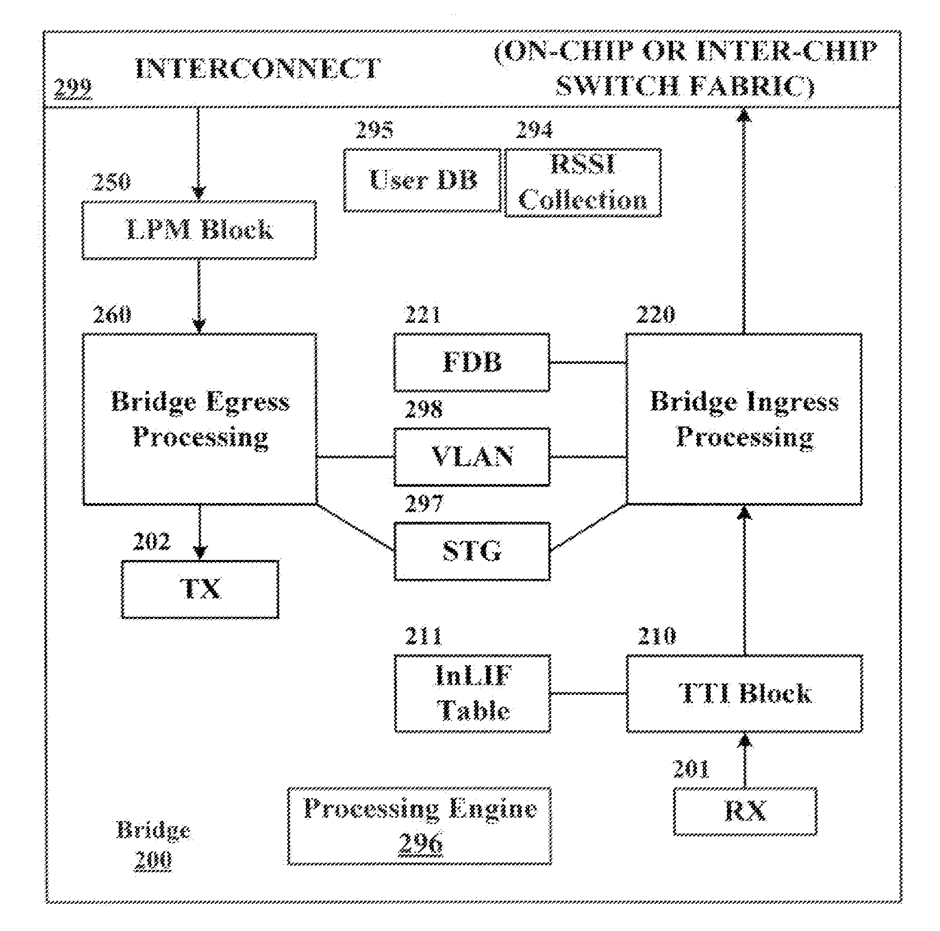
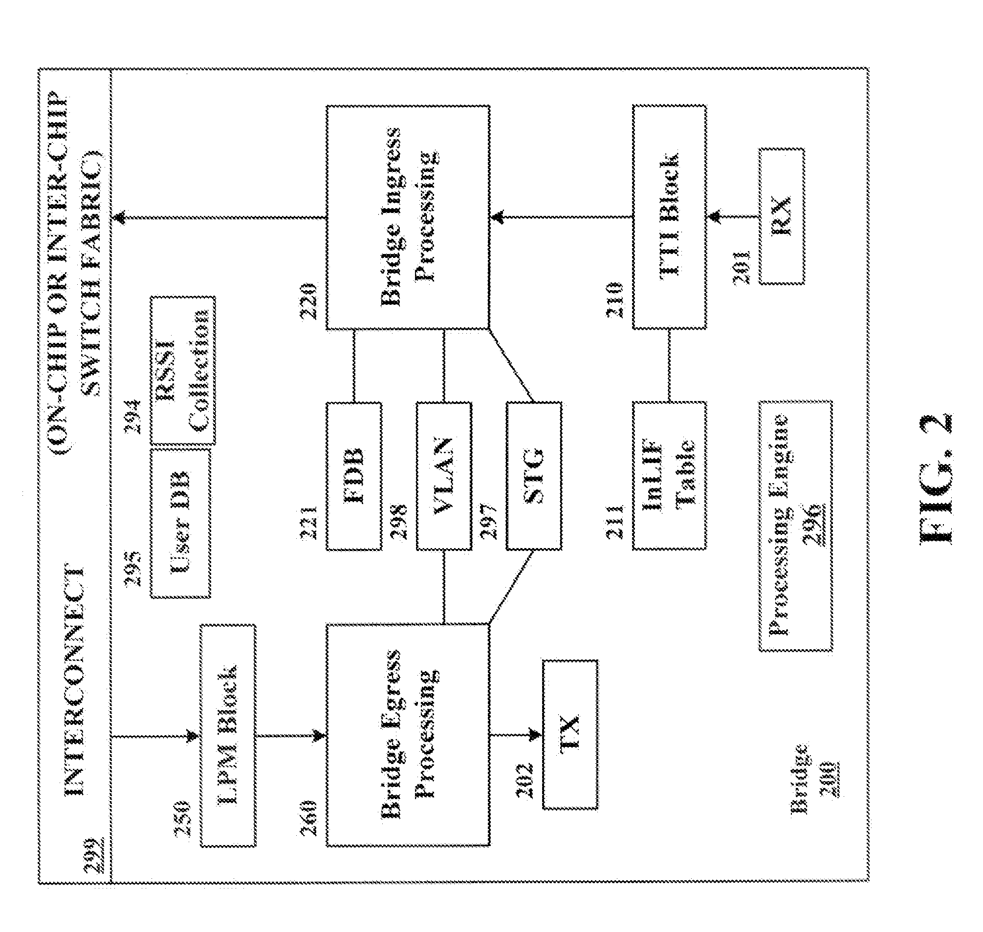
The present invention provides a system and method for logical bridging, which allows a logical bridge to assign source logical port information to a data packet based on its characteristics, learn the source address, and forward it to a logical egress port. The logical egress port is then mapped to a physical egress port at which the data packet is to be egressed. A tunnel interface may optionally be applied to the data packet upon egress. This technology overcomes the shortcomings of conventional technology and facilitates more efficient data transmission.

Problems solved by technology

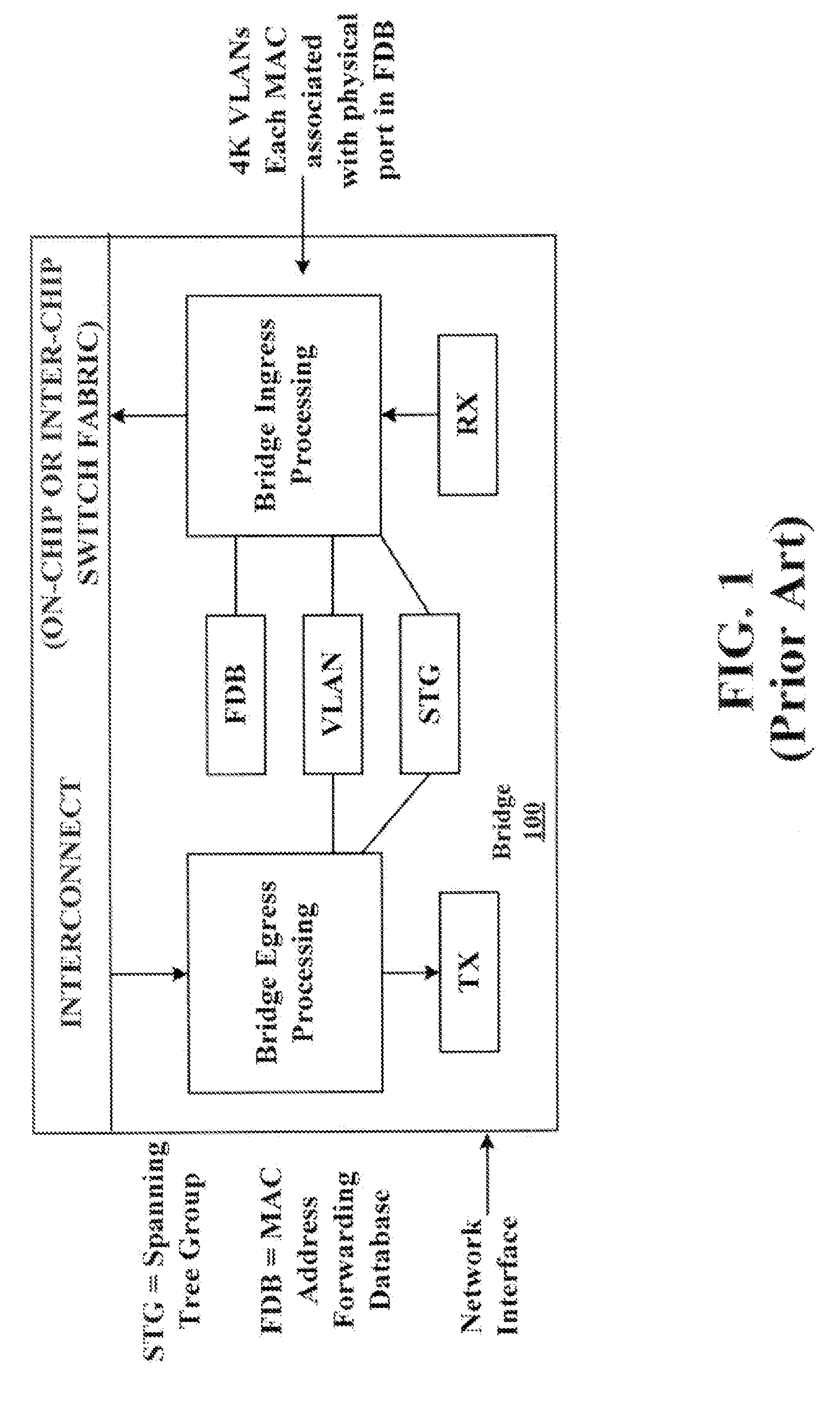
These architectures are generally limited with respect to the number of service instances, i.e., discrete VLANs, that they are able to handle.
While RSSI data may be useful in various ways, conventional bridging hardware does not extract RSSI information tram data packets originating from wireless networks.

Method used


Image

  • Logical bridging system and method
  • Logical bridging system and method
  • Logical bridging system and method

Examples


Embodiment Construction

Introduction

[0017]Embodiments of the present invention may have utility in the field of network switches such as, for example, Ethernet switches. The disclosed system and method may be employed in connection with various local area network (LAN) applications and architectures that support virtual networking strategies such as virtual LAN (VLAN), virtual private network (VPN), and virtual private LAN service (VPLS) technologies. It is noted that a layer 2 VPN may be implemented using VPLS techniques.

[0018]A switch may be a boundary (or edge) device disposed between two types of networks in some applications. For example, a switch may bridge a service provider backbone network (e.g., that forwards traffic based on traffic service) and an access network (e.g., that forwards traffic based on user ID). Aspects of the present invention are generally directed to such switching devices that execute bridging functionality and allow data communication across disparate network domains.

[0019]Wh...


PUM


Abstract

A system and method of extending a standard bridge to enable execution of logical bridging functionality are disclosed. In some implementations, a logical bridge may assign source logical port information to a data packet based on characteristics of the data packet, employ the source logical port information to learn the source address and to forward the data packet to a logical egress port, and map the logical egress port to a physical egress port at which the data packet is to be egressed. A tunnel interface may optionally be applied to a data packet upon egress.

Description

CROSS-REFERENCE TO RELATED APPLICATIONS[0001]The present application claims the benefit of the following co-pending U.S. provisional applications: Ser. No. 60 / 916,065, filed May 4, 2007, entitled “Local Bridge implementation;” and Ser. No. 60 / 889,809, filed Feb. 14, 2007, entitled “Prestera DX Support for CAPWAP and WLAN Switching.” The disclosures of the foregoing applications are incorporated herein by reference in their entireties.Background[0002]1. Field of the Invention[0003]Aspects of the present invention relate generally to data communications, and more particularly to a system and method of extending a standard bridge to execute logical bridging functionality.[0004]2. Description of Related Art[0005]Various types of virtual networking technologies are generally known. One popular communications standard for use in connection with virtual network implementations is the institute of Electrical and Electronics Engineers (IEEE) 802.1Q standard for Ethernet applications. In acco...

Claims


Application Information

Patent Timeline
Patent Type & Authority Applications(United States)
IPC IPC(8): H04L12/56H04L45/02
CPCH04L12/4625H04L45/00H04L45/60H04L45/08H04L49/351H04L12/46H04L45/04H04L49/109
Inventor MELMAN, DAVIDARAD, NIRBSHARA, NAFEA
Owner MARVELL ISRAEL MISL
Why Eureka
Eureka Blog
Learn More