Oscillator with acoustic surface wave resonators
a surface wave and oscillator technology, applied in the field of electric engineering and electronics, can solve the problems of insufficient stability of oscillators, excessive high cost, nonlinear
- Summary
- Abstract
- Description
- Claims
- Application Information
AI Technical Summary
Benefits of technology
Problems solved by technology
Method used
Image
Examples
example 1
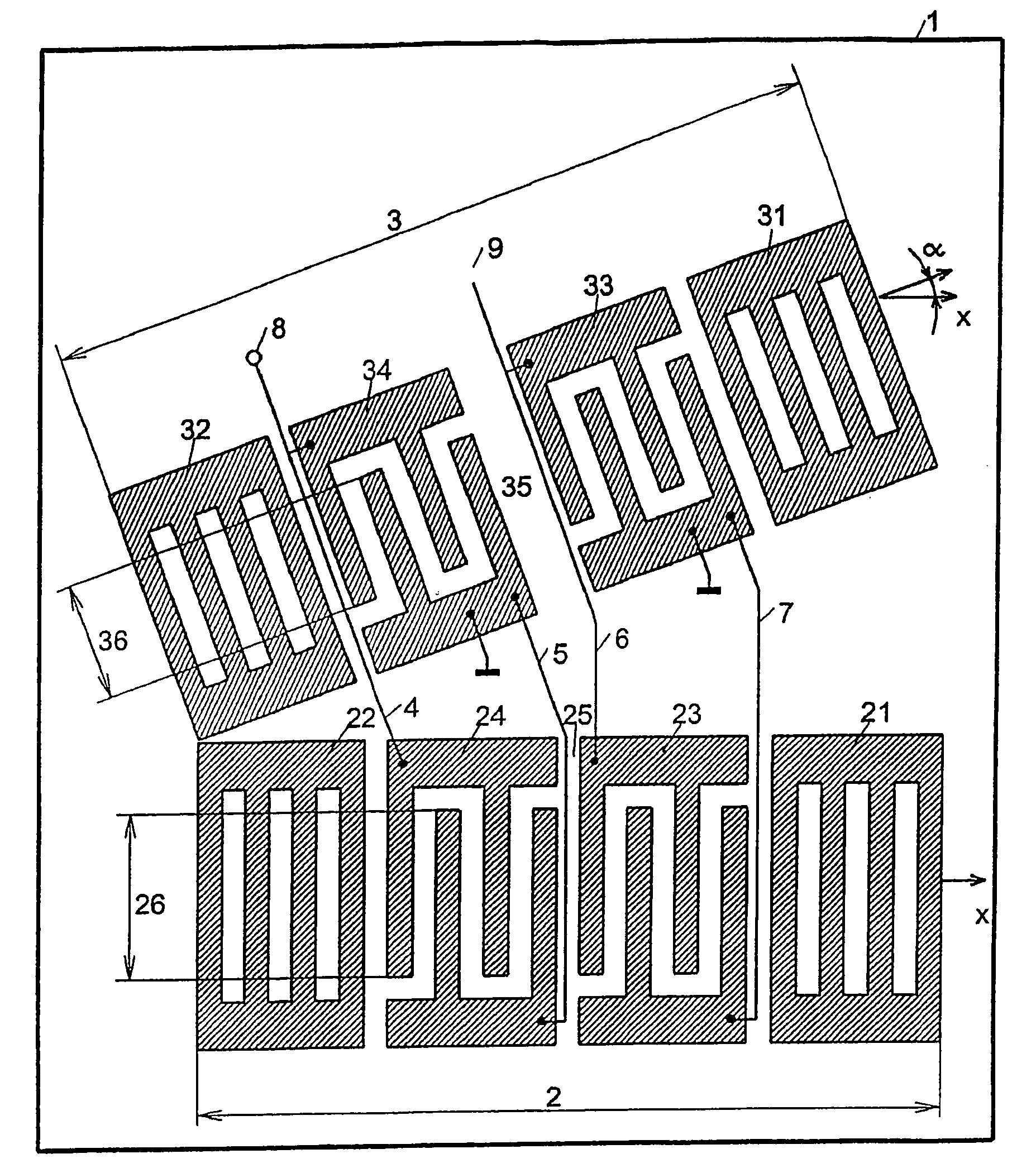
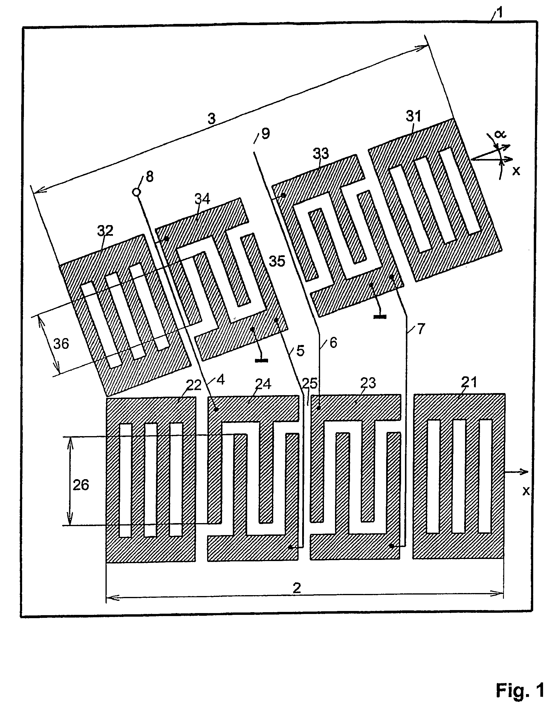
[0046]The oscillator, shown in FIG. 1, consists of a resonator composite as frequency-determining element and a feedback from the output to the input of the composite, which is not shown in the drawing and contains an amplifier. It is assumed that the phase of this feedback is equal to zero. The properties of the resonator composite are described in the following.
[0047]Two two-gate surface wave resonators 2; 3, assembled from reflectors 21; 22 and interdigital converters 23; 24 or from reflectors 31; 32 and interdigital converters 33; 34, are disposed on a substrate 1, which is an ST section of quartz. The two-gate surface wave resonators 2; 3 form a resonator composite. The spreading direction of the two-gate resonator 2, that is, the direction perpendicular to the teeth of the converter 23; 24 and to the strips of the reflectors 21; 22, is aligned parallel to the crystallographic x axis of quartz. For this reason, the temperature dependence of the synchronous frequency of the two-...
example 2
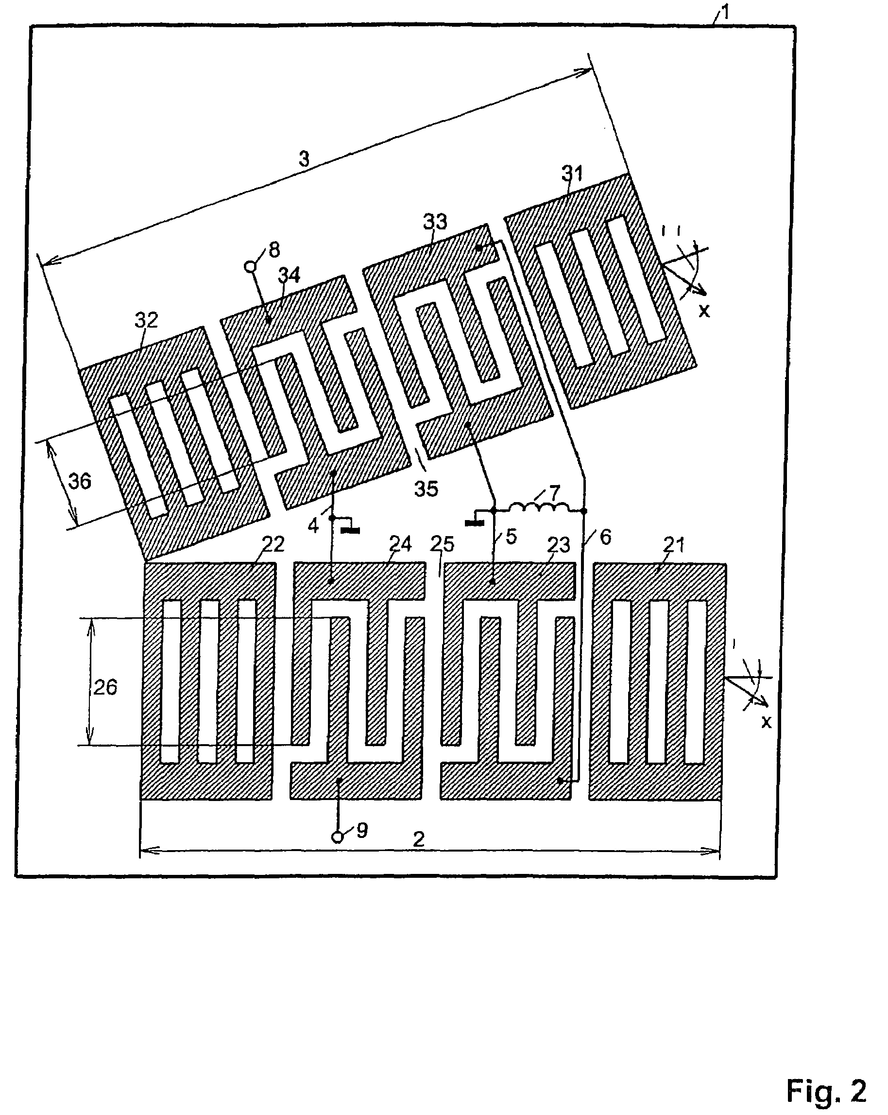
[0050]This example relates to the oscillator shown in FIG. 2. This oscillator consists of a resonator composite as frequency determining element and a feedback from the output to the input of the composite. The feedback contains an amplifier and is not shown. It is assumed that the phase of this feedback is equal to zero. The properties of this resonator composite are described in the following.
[0051]On a substrate 1, which is an ST section of quartz, the surface wave resonators 2; 3, assembled from the reflectors 21; 22 and the interdigital converter 24 and from the reflectors 31; 32 and the interdigital converter 34, are disposed. In addition, a coupling converter 23 or 33 is disposed in the surface wave resonator 2 or 3 between the converter 24 or 34 and the reflector 21 or 31. The surface wave resonators 2; 3 form a resonator composite. The electrodes consist of a layer of aluminum 300 nm thick. The spreading direction of the surface wave resonator 2, that is, the direction perp...
example 3
[0053]This example relates to the oscillator with two separate substrates, which is shown in FIG. 3. A surface wave resonator 2, assembled from the reflectors 21; 22 and the interdigital converter 34, is disposed here on a first substrate 10. In addition, a coupling converter 23 is disposed in the surface wave resonator 2 between the converter 24 and the reflector 21. A surface wave resonator 3, assembled from the reflectors 31; 32 and the interdigital converter 34, is disposed on a second substrate 1. In addition, a coupling converter 33 is disposed in the surface wave resonator 3 between the converter 34 and the reflector 31. The surface wave resonators 2; 3 form a resonator composite. The substrate 1 as well as the substrate 10 is an ST section of quartz. In this case, a spreading direction of the surface wave resonator 2, that is, the direction perpendicular to the teeth of the coupling converter 23 and of the converter 24 and to the strips of the reflector 21; 22, is inclined a...
PUM
 Abstract
Description
Claims
Application Information
 - R&D
- Intellectual Property
- Life Sciences
- Materials
- Tech Scout
- Unparalleled Data Quality
- Higher Quality Content
- 60% Fewer Hallucinations
Browse by: Latest US Patents, China's latest patents, Technical Efficacy Thesaurus, Application Domain, Technology Topic, Popular Technical Reports.
© 2025 PatSnap. All rights reserved.Legal|Privacy policy|Modern Slavery Act Transparency Statement|Sitemap|About US| Contact US: help@patsnap.com


