Integrated circuit television receiver arrangement

a television receiver and integrated circuit technology, applied in the field of receivers, can solve the problems of limited stringent requirements of the receiver, and limited available space as well as current and/or voltage supply, so as to reduce the required space, reduce physical height, and low voltage

Inactive Publication Date: 2009-12-15
INFINEON TECH AG
View PDF26 Cites 3 Cited by
  • Summary
  • Abstract
  • Description
  • Claims
  • Application Information

AI Technical Summary

Benefits of technology

[0028]The receiver arrangement according to the invention is preferably used in a receiver for digital television signals, and in particular for terrestrial digital television. The formation of a number of components as an integrated circuit in a semiconductor body reduces the required space.
[0029]In particular, the physical height is reduced by the use of surface mounted devices, for example SMD coils. Owing to the low voltage that is used and the low power consumption, the present receiver arrangement is particularly suitable for use in mobile appliances, for example in notebooks, PDAs or mobile telephones.
[0030]The supply and production of a correction signal from correction values which are stored in a memory means that there is no need for additional mechanical trimming during the manufacture of the receiver arrangement according to the invention, thus making it possible for the components that are required for the filter to be in the form of space-saving SMD elements. This reduces the production costs. The correction values may be determined in advance in a suitable measurement process, and may be stored in the memory.

Problems solved by technology

The development of digital television distribution services (DVB: Digital Video Broadcast) results in stringent requirements for the receiver, owing to the complex transmission signal.
In systems such as these, for example notebooks or laptops, the available space as well as the current and / or voltage supply are limited.

Method used


Image

  • Integrated circuit television receiver arrangement
  • Integrated circuit television receiver arrangement
  • Integrated circuit television receiver arrangement

Examples


Embodiment Construction

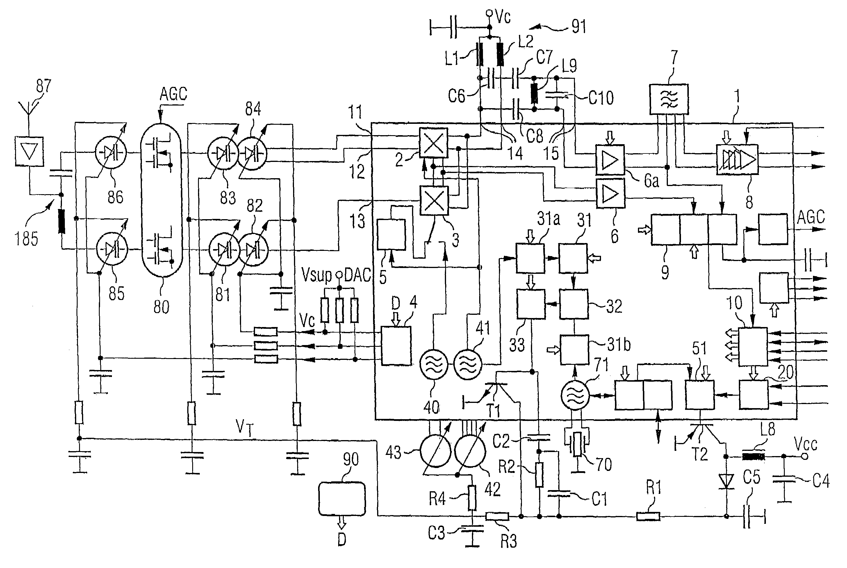
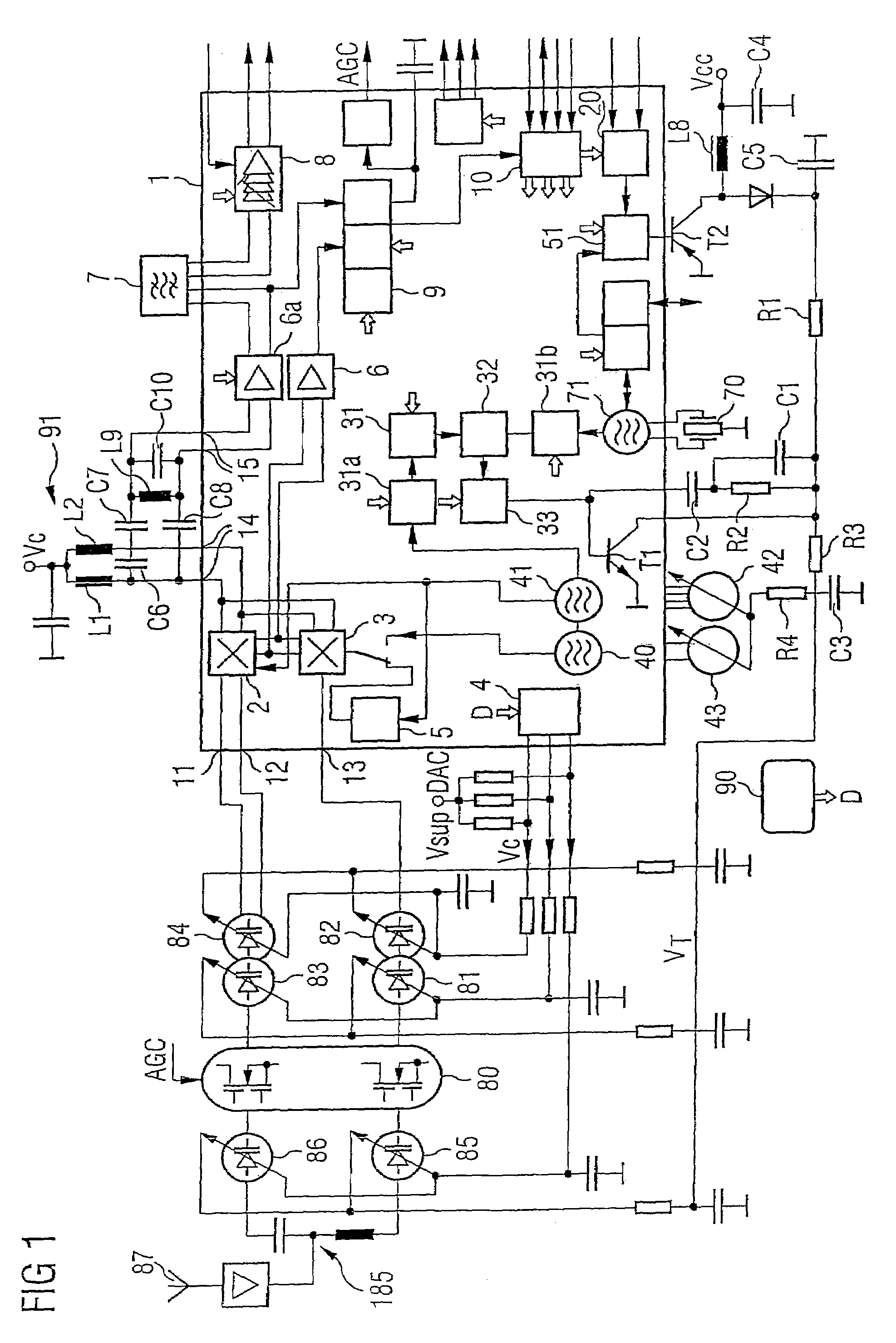
[0044]FIG. 1 shows one exemplary embodiment of a receiver arrangement according to the invention for the reception and signal processing of two frequency bands. The structure of this receiver arrangement may, however, be extended by arranging further receiver paths in parallel, so that different frequency bands can be received. In the arrangement according to the invention, two or more components are implemented in a common semiconductor body 1, which in the exemplary embodiment is produced using silicon semiconductor technology. The components are thus in the form of integrated circuits in a single semiconductor body. The semiconductor body 1 has two or more connections on its surface, and these are referred to as contact pads. The contact pads are connected via lines to discrete components. At the same time, the contact pads lead to the individual integrated circuits of the receiver arrangement within the semiconductor body.

[0045]The receiver arrangement in the exemplary embodimen...


PUM


Abstract

According to one or more aspects of the present invention, a receiver arrangement is disclosed that is configured to receive digital television signals. The receiver arrangement has at least one first frequency conversion device with the signal input, a local oscillator input and an output. The at least one first frequency conversion device is designed to convert a signal which is applied to the input side to an intermediate frequency. A first amplifier is also provided and is designed with amplification in order to compensate for the signal level loss in a filter which is connected downstream from the first amplifier. The first amplifier is coupled to the output of the frequency conversion device. An intermediate-frequency amplifier with a variable gain factor is also provided, and is coupled to the first amplifier. At least the at least one first frequency conversion device the first amplifier are formed in a common semiconductor body.

Description

REFERENCE TO RELATED APPLICATIONS[0001]This application claims the benefit of the priority date of German application DE 10 2004 034 274.1, filed on Jul. 15, 2004, the contents of which are herein incorporated by reference in its entirety.FIELD OF THE INVENTION[0002]The present invention relates generally to receivers, and more particularly to a receiver arrangement configured to receive digital television signals.BACKGROUND OF THE INVENTION[0003]The development of digital television distribution services (DVB: Digital Video Broadcast) results in stringent requirements for the receiver, owing to the complex transmission signal. In addition to high frequency selectivity, maintenance of a high degree of linearity is also required in order to avoid errors in the transmitted and received data with the OFDM transmission method that is used. Very good phase noise is of major importance for the reception of digital signals with OFDM modulation, while the noise factor or the signal-to-noise...

Claims


Application Information

Patent Timeline
Patent Type & Authority Patents(United States)
IPC IPC(8): H04N5/44H04N5/455
CPCH03D7/1433H03G3/3068H03J3/32H03L7/0898H03L7/093H03L7/107H04N21/42607H04N5/4446H03D7/1408H03D7/1458H04N21/41407H04N5/4401H03D2200/0025H04N21/426
Inventor KRUG, ERWINPFLAUM, BERND
Owner INFINEON TECH AG
Why Eureka
Try Eureka