
High speed controller area network receiver having improved EMI immunity

a technology of emi and receiver, which is applied in the field of high-speed controller area network receivers, can solve the problems of emi creating errors in reading data, delay in the receiver affecting the speed of the transceiver,

Active Publication Date: 2009-07-28
TEXAS INSTR INC
View PDF11 Cites 26 Cited by
  • Summary
  • Abstract
  • Description
  • Claims
  • Application Information

AI Technical Summary

Benefits of technology

The patent describes a new CAN receiver design that improves immunity against EMI interference and increases the speed of the receiver. The design uses a voltage divider to divide the CAN bus signal by a predetermined factor, which is then amplified by a front end amplifier. This improves common mode rejection, which helps prevent errors in reading the data. The technical effect of this design is better immunity against EMI interference and faster operation compared to conventional designs.

Problems solved by technology

Accordingly, delay in the receiver affects the speed of the transceiver.
EMI creates errors in reading the data.

Method used


Image

  • High speed controller area network receiver having improved EMI immunity
  • High speed controller area network receiver having improved EMI immunity
  • High speed controller area network receiver having improved EMI immunity

Examples


Embodiment Construction

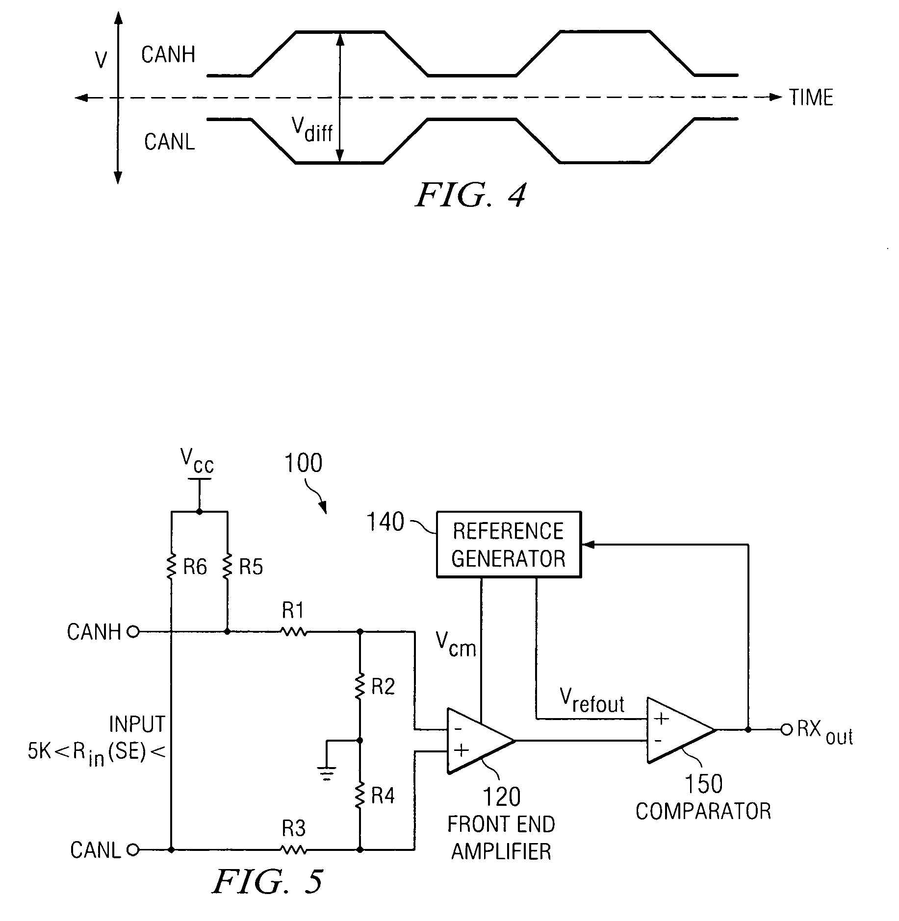
[0023]One or more exemplary implementations of the present invention will now be described with reference to the attached drawings, wherein like reference numerals are used to refer to like elements throughout. The various aspects of the invention are illustrated below in a CAN receiver, although the invention and the appended claims are not limited to the illustrated examples.

[0024]One of the design challenges was to design an architecture that may be powered by a 5 volt supply voltage VCC and have a common mode voltage range that could possibly extend from +20 V to −20 V. The novel CAN receiver had to possess a good amount of rejection. Thereby, the basic challenge was that the input signal, CANH and CANL, represent signal that are a significant amount of voltage greater than the supply voltage VCC and signal to noise ratio could deteriorate if the input signal is divided down too much to avoid the high input common mode signal.

[0025]FIGS. 5 and 6 illustrates a block diagram of th...


PUM


Abstract

A CAN receiver architecture design that provides better immunity against EMI interference than conventional designs is disclosed herein. This CAN receiver includes a voltage divider network connected to a front-end amplifier for dividing down the input signal from a two wire line by a predetermined amount and amplifying the signal by the same predetermined amount. The front-end amplifier generates the common-mode voltage of the input signal for a reference generator that determines the logic level of the incoming signal and subtracts a bandgap voltage reference from the common-mode voltage. A comparator compares the difference between the output of the front-end amplifier and the resultant signal generated by the reference generator to generate an output signal for the receiver. This CAN receiver architecture is faster than conventional designs and possesses an improved common-mode rejection, while operating over a wide input common mode range.

Description

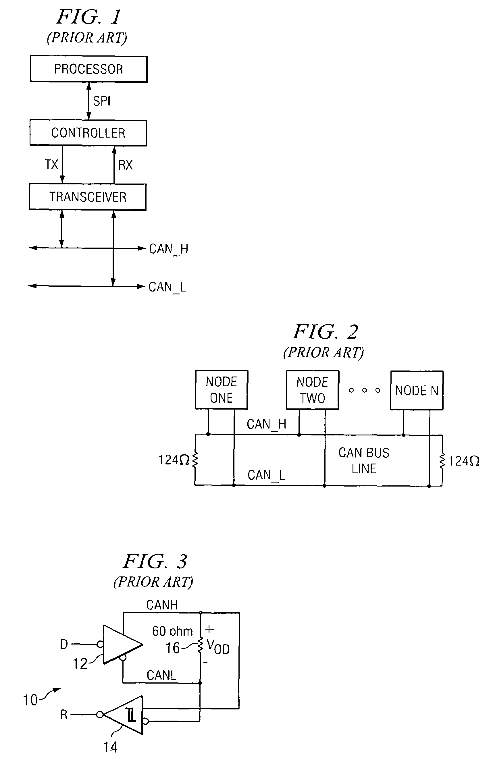
[0001]This application claims the benefit of Application Ser. No. 60 / 640,115 filed Dec. 28, 2004, which is incorporated herein by reference.FIELD OF THE INVENTION[0002]The present invention relates to controller area network transceivers and, more particularly, to a controller area network receiver having an improved EMI immunity.BACKGROUND OF THE INVENTION[0003]A controller area network (CAN) bus, such as that compliant with the ISO 11898 standard, is used in several systems including industrial, automotive, robotic, and motor control systems to provide a serial communication physical layer. The robust CAN bus provides low power requirements, space savings and reduced resources. As shown in FIG. 1, a CAN node is comprised of three basic parts: a processor, a network controller, and a transceiver. The transceiver interfaces the single-ended CAN controller with the differential CAN bus. The bus, as shown in FIG. 2, includes multiple nodes that transmit messages on-demand by any node ...

Claims


Application Information

Patent Timeline
Patent Type & Authority Patents(United States)
IPC IPC(8): H03K3/00
CPCG06F13/4072H04L12/40013H04L25/0276H04L12/40032H04L2012/40273H04L2012/40215
Inventor TRICHY, NARASIMHAN R.CHEN, WAYNE TIEN-FENG
Owner TEXAS INSTR INC
Learn More