Pressure control butterfly valve

一种压力控制、蝶式的技术,应用在压力控制领域,能够解决真空配管5安装空间变大、构造复杂等问题,达到优异防漏性能、安装宽度减小、高速且高精度压力控制的效果

Active Publication Date: 2010-02-10
KAISHI SCT CO LTD
View PDF1 Cites 16 Cited by
  • Summary
  • Abstract
  • Description
  • Claims
  • Application Information

AI Technical Summary

Problems solved by technology

[0031] in addition, Figure 11 Although the valve system 1 can adjust the exhaust time of soft exhaust and control the pressure of the process gas, the structure is complicated, and there is a problem that the installation space relative to the vacuum piping 5 becomes larger.

Method used


Image

  • Pressure control butterfly valve
  • Pressure control butterfly valve
  • Pressure control butterfly valve

Examples


Embodiment Construction

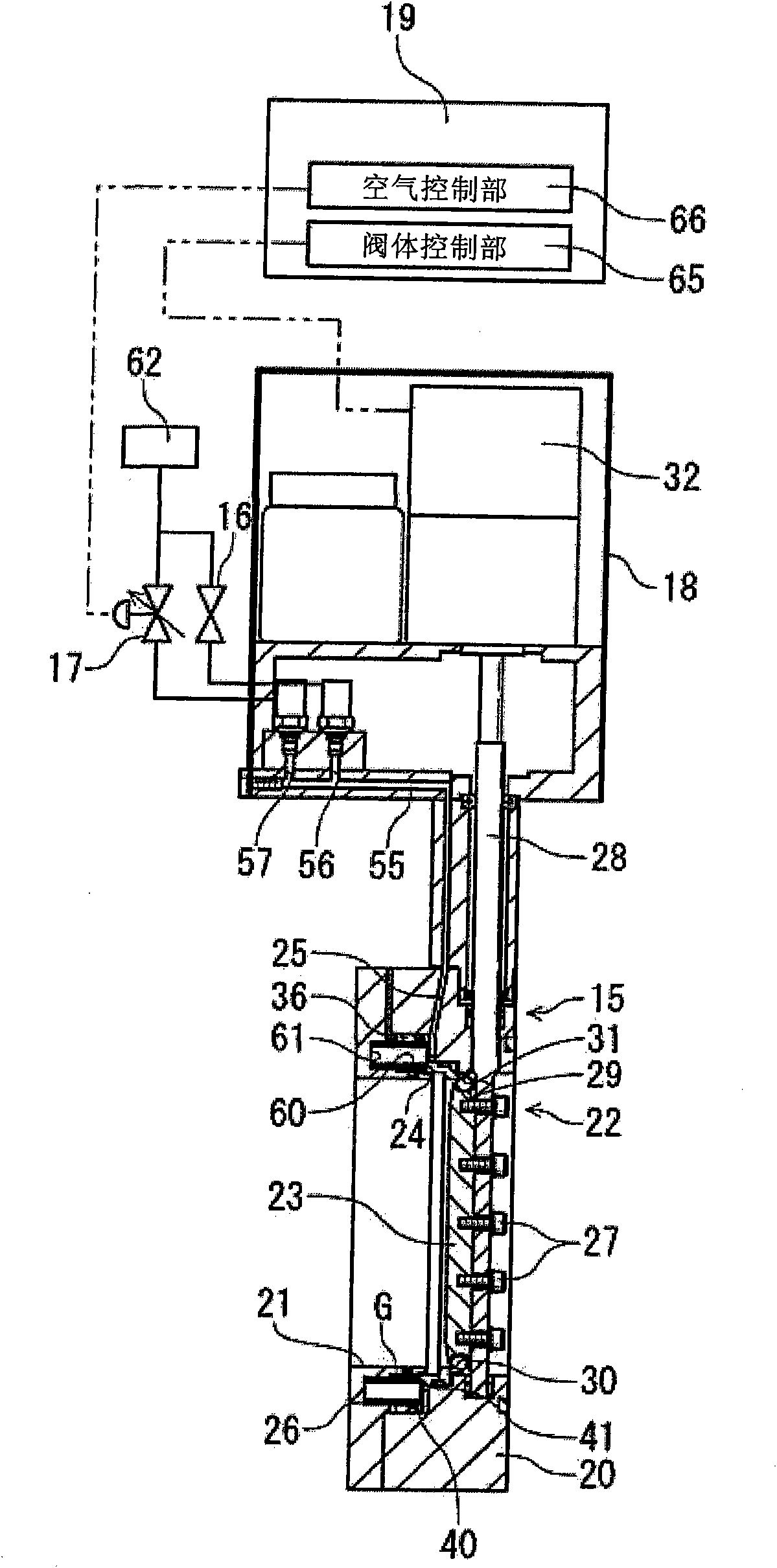
[0080] Hereinafter, a preferred embodiment of the butterfly pressure control valve of the present invention will be described in detail with reference to the accompanying drawings. Such as Picture 10 As shown, for example, in the pipeline 10 in the semiconductor manufacturing process, the butterfly pressure control valve of the present invention is connected between the vacuum chamber 11 and the vacuum pump 12, and includes a valve body 15 and a solenoid valve 16 connected to the valve body 15 , Electro-pneumatic regulator 17, actuator 18 and controller 19.

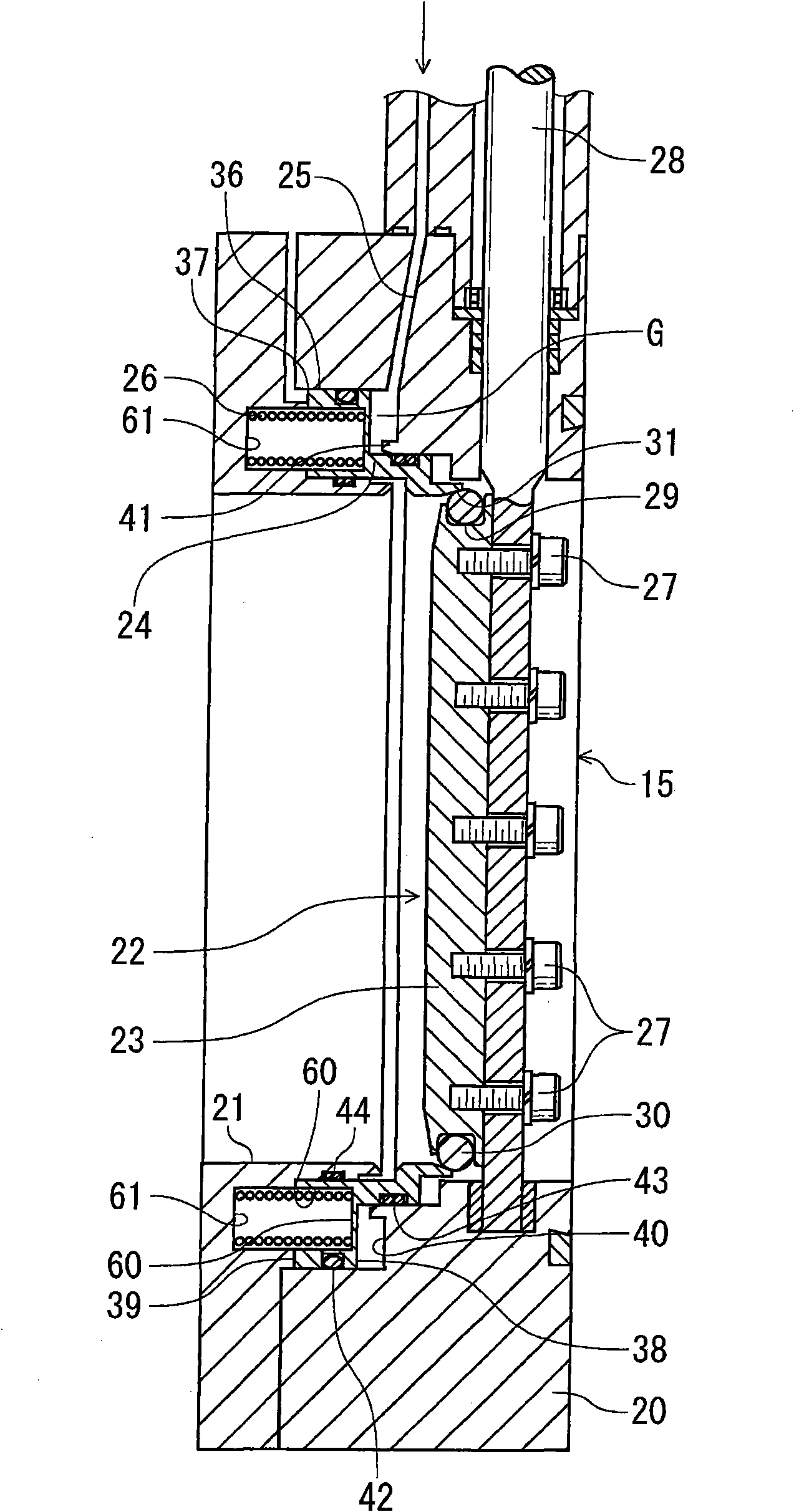
[0081] in figure 1 Here, one embodiment of the butterfly pressure control valve of the present invention is shown. A flow path 21 is formed in the main body 20 of the valve main body 15, and a valve opening and closing mechanism 22 that opens and closes the flow path 21 is provided. The valve opening and closing mechanism 22 has a valve body 23, a seat ring 24, an air flow path 25 and a spring 26.

[0082] In the valve op...


PUM


Abstract

The invention provides a pressure control valve which is pressure control butterfly valve suitable for controlling the internal pressure of the vacuum region, capable of making the space for installation to be small, capable of making high-speed control with a small operation force, maintaining a valve-closed state during valve-closing to attain high sealability, during valve-opening, capable of accurately controlling flow rates from a micro flow rate to a large flow rate, capable of fulfilling the same durability with the ordinary butterfly valves, and capable of solely fulfilling an isolation function so as to control the discharge air time of slowpump from atmospheric pressure to rough vacuum. The pressure control butterfly valve comprises a valve opening / closing mechanism. The valve opening / closing mechanism is for nonslidably rotating the valve disc from which the seat ring has been separated by supply of air to the airflow path and for allowing the seat ring to abut on and separate from the valve disc by means of the supply of air to the airflow path and the biasing force of the spring when the valve disc has been rotated to a valve-closed state, thereby controlling pressurein the flow passage.

Description

Technical field [0001] The present invention relates to a high-durability butterfly pressure control valve with isolation function, which is a butterfly pressure control valve used to ensure high sealing performance and control a small flow of exhaust in the semiconductor manufacturing process, and is particularly suitable for Soft exhaust control from atmospheric pressure to low vacuum, and pressure control to stably control process gas pressure at high speed from a vacuum state. Background technique [0002] In the past, for example, in the semiconductor manufacturing process, the following proposal has been proposed in which a pressure control valve with isolation function is provided between a vacuum chamber as a vacuum container and a vacuum pump. A vacuum isolation valve (hereinafter referred to as an isolation valve) is a valve that performs exhaust from a vacuum chamber and stops the exhaust, and controls the pressure inside the vacuum chamber so as to be close to a prede...

Claims


Application Information

Patent Timeline
Patent Type & Authority Applications(China)
IPC IPC(8): F16K1/22
CPCF16K1/2266F16K39/026F16K51/02F16K1/42F16K1/46F16K27/0218F16K39/028H01L21/02
Inventor 岩渕俊昭
Owner KAISHI SCT CO LTD
Why Eureka
Try Eureka