
Coatings, materials, articles, and methods of making thereof

a technology of coatings and materials, applied in the field of coatings, materials, articles, and methods of making thereof, can solve the problems of material failure, complex interaction between the microstructure, and the inability of the current available deposition method to manipulate all the above-described microstructural features

Active Publication Date: 2009-07-21
UNIV OF CONNECTICUT +2
View PDF33 Cites 36 Cited by
  • Summary
  • Abstract
  • Description
  • Claims
  • Application Information

AI Technical Summary

Benefits of technology

This method enables the production of materials with splats less than 2 micrometers in diameter, porosity of 1-50 volume percent, and vertical cracks, suitable for a wide range of applications including thermal barrier coatings and structural forms, demonstrating improved durability and thermal cycling performance compared to conventional methods.

Problems solved by technology

Thus it is clear that there is a complex interaction between the microstructure, composition, end use and the method of making the coating or material.
The size of the splat boundary is related to the size of the splat and large splat boundaries may result in lateral cracking, potentially causing material failure.
None of the currently available methods of deposition is capable of manipulating all the above-described microstructural features.

Method used


Image

  • Coatings, materials, articles, and methods of making thereof
  • Coatings, materials, articles, and methods of making thereof
  • Coatings, materials, articles, and methods of making thereof

Examples


example 1

ZrO2+7 wt % Y2O3 (7YSZ) Thermal Barrier Coating

[0078]The precursor solution was prepared as follows. Zirconium acetate was dissolved in a weak organic acid and then mixed with distilled water to form a solution having a pH of 3-5. The Zr solution was mixed with yttrium nitrate to form a precursor solution. Multiple coatings were formed by deposition of the precursor solution according to the parameters in Table 2.

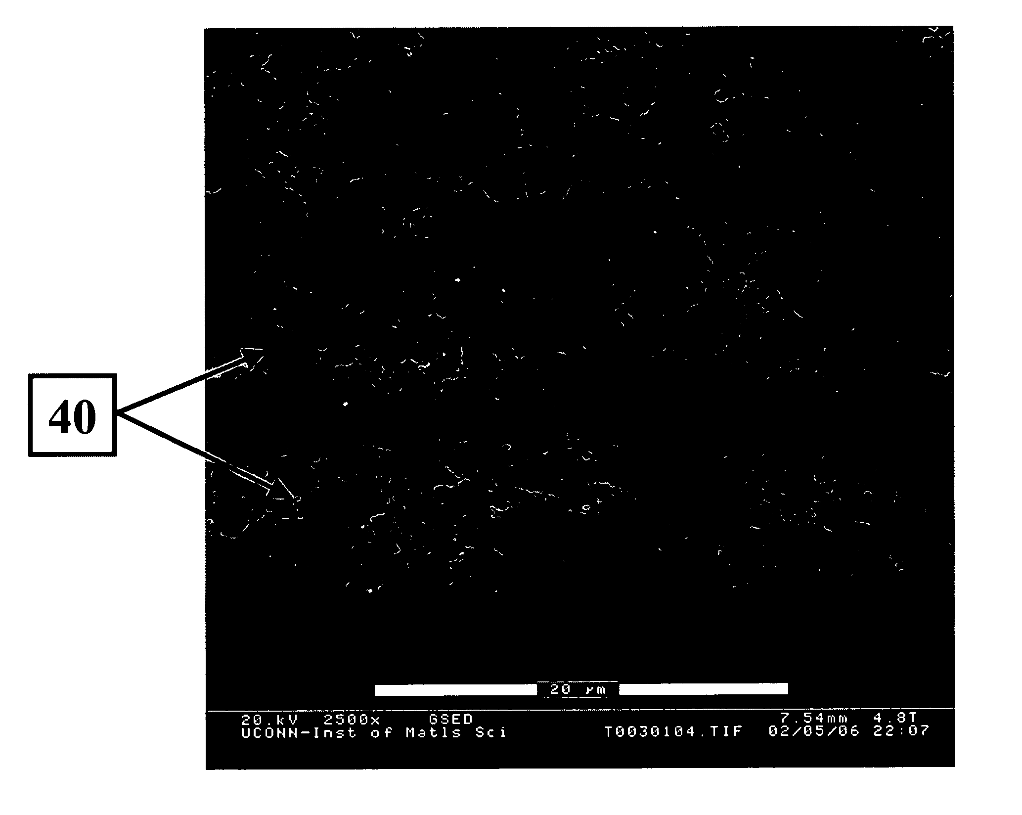
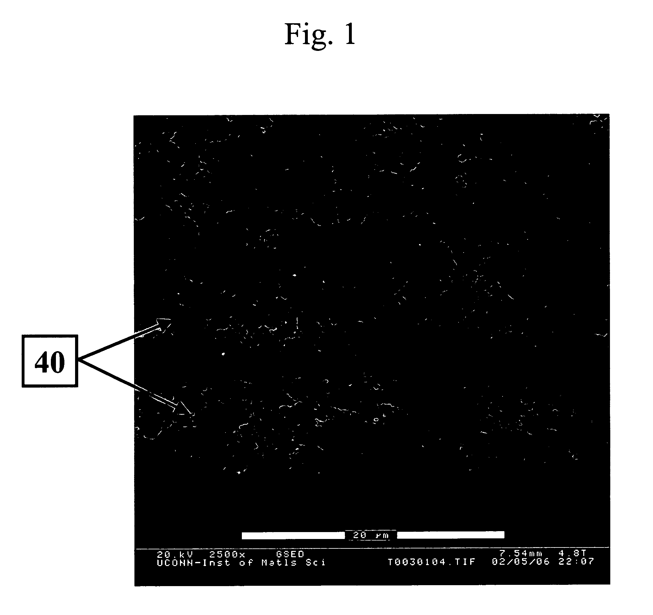
[0079]The solution plasma spray deposited 7YSZ had a porosity of about 15 volume % to about 30 volume % of the total volume of the coating and a thickness of about 300 micrometers to as much as 3,000 micrometers. The 7YSZ coating was well bonded to the substrate, contained fine splats, and contained some spaced vertical cracks as well as micrometer and nanometer-sized porosity. FIG. 3 shows the splats and vertical cracking. Moreover, the 7YSZ coating structure was verified to be stable in retaining nanometer grain size and reducing sintering during long-term exposure at an ...

example 2

ZrO2+20 wt % Y2O3 (20YSZ) Electrolyte Layer

[0081]The precursor solution was prepared by dissolving zirconium acetate in acetic acid and then mixing with distilled water with a pH of 3-5. Then yttrium nitrate was mixed with the solution to form the precursor solution. Multiple coatings were formed by deposition of the precursor solution according to the parameters in Table 2.

[0082]The solution plasma spray deposited 20YSZ had a porosity of less than about 2 volume % of the total volume of the coating (FIG. 6A). The coating was crack-free and adherent to the substrate when its thickness was below 100 micrometers. However, vertical cracks and coating exfoliation occurred in coatings having a thickness more than 200 micrometers. The coating comprised cubic-ZrO2.

[0083]A stainless steel strip was coated with a solution plasma spray-applied 20YSZ coating, then bent into 90° angles. As shown in FIG. 10, no spallation in the deformed area was found with the exception of minor cracks and slig...

example 3

Al2O3 Coating

[0084]The precursor solution was prepared by dissolving aluminum nitrate in distilled water to form a 1.0 mole precursor solution. Coatings were formed by deposition of the precursor solution according to the parameters in Table 2.


PUM

PropertyMeasurementUnit
diameteraaaaaaaaaa
thicknessaaaaaaaaaa
diameteraaaaaaaaaa

Abstract

A thermal spray process comprises injecting precursor solution droplets into the hot zone of the thermal spray flame. Also described are materials resulting from the process.

Description

CROSS REFERENCE TO RELATED APPLICATIONS[0001]This application claims priority to Provisional Application Serial No. 60 / 439,288 filed on Jan. 10, 2003, which incorporated by reference herein.STATEMENT REGARDING FEDERALLY SPONSORED RESEARCH & DEVELOPMENT[0002]The U.S. Government has certain rights in this invention pursuant to Office of Naval Research grant numbers N00014-98-C-0010, N00014-02-1-0171.BACKGROUND[0003]There is a wide variety of methods for forming a coating or deposited material. Methods include chemical vapor deposition, physical vapor deposition, laser assisted pyrolysis deposition, electron-beam physical vapor deposition and thermal spray. The coating or material produced by these methods can vary significantly in microstructure from method to method. The microstructure of the coating or material, as well as its composition, has a significant impact the physical and mechanical properties, as well as the end use. Thus it is clear that there is a complex interaction bet...

Claims


Application Information

Patent Timeline
Patent Type & Authority Patents(United States)
IPC IPC(8): B32B5/18B32B5/02B32B5/14B32B5/22C04B35/50C23C4/12H01M8/12
CPCB82Y30/00C04B35/486C04B35/50C23C4/121H01M4/9025H01M4/9033H01M8/1253C04B35/01Y10T428/268C04B2235/3206C04B2235/3213C04B2235/3225C04B2235/3227C04B2235/3229C04B2235/3286C04B2235/449C04B2235/77C04B2235/781H01M2008/1293Y02E60/521Y02E60/525Y02T50/67Y10T428/25Y10T428/26C23C4/123Y10T428/249986Y10T428/249953Y10T428/249967Y10T428/24997Y02E60/50Y02P70/50Y02T50/60
Inventor GELL, MAURICEMA, XINQINGJORDAN, ERICPADTURE, NITIN P.XIE, LIANGDEXIAO, DANNYDECARMINE, ANTHONY
Owner UNIV OF CONNECTICUT
Learn More