
Extreme UV radiation exposure tool and extreme UV radiation source device

a radiation source and tool technology, applied in the field of extreme uv radiation exposure tools and extreme uv radiation source devices, can solve the problems of difficult formation of discharge depending on the electrode arrangement, low radiation transparency, and inability to reduce projection using a transparent optical system, etc., and achieve high efficiency

Active Publication Date: 2009-05-19
USHIO DENKI KK
View PDF15 Cites 2 Cited by
  • Summary
  • Abstract
  • Description
  • Claims
  • Application Information

AI Technical Summary

Benefits of technology

This approach allows for high-efficiency elimination of adverse radiation outside the 13.5 nm band without reducing the intensity of EUV radiation, thereby enhancing exposure performance and maintaining desired image resolution.

Problems solved by technology

Since material for EUV radiation has very low transparency, reducing projection using a transparent optical system cannot be achieved.
Under such a low pressure, the formation of a discharge depending on the electrode arrangement is made difficult.
As a result, there are also cases in which the output of the EUV radiation becomes unstable.
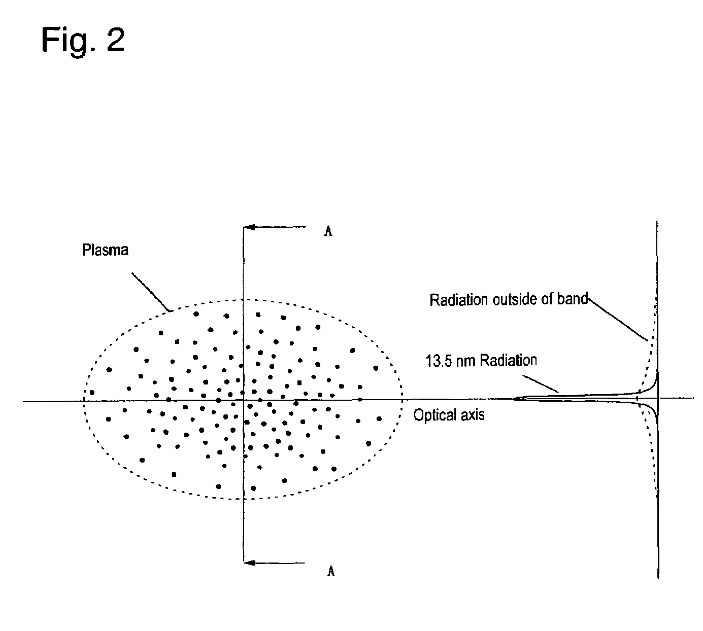
Specifically, if there is radiation in the wavelength band from 130 nm to 400 nm (UV radiation), especially radiation in the wavelength band from 150 nm to 300 nm, exposure with the desired resolution is not possible.
This means that radiation in a wavelength band from 150 nm to 300 nm causes a reduction of the image resolution during exposure.
On the other hand, if radiation in the wavelength band of at least 800 nm (IR radiation) reaches the workpiece through an exposure optical system using a reflection optical system and is absorbed, thermal deformation of the workpiece itself is caused.
The exposure surface of the workpiece therefore assumes an unwanted shape.
As was described above, radiation which is outside the band causes a degradation of the exposure performance of an EUV exposure tool.
Extraction of EUV radiation with the intensity required for exposure from an EUV radiation source device is therefore accompanied by difficulties.
However, since a diffraction grating is an optical element with which spectral decomposition takes place using angular dispersion of the wavelength, in the case of using radiation from an EUV radiation source device with low directivity, in contrast to laser radiation, it is necessary on the radiation incidence side of the diffraction grating to use a slit in order to limit the angle of incidence of the radiation emitted by the EUV radiation source device into the diffraction grating.
That is, with consideration of the intensity of the EUV radiation which is necessary for exposure, use of a diffraction grating as a wavelength selection element is virtually impossible in practice.
As was described above, extraction of the EUV radiation with a wavelength of 13.5 nm with the intensity required for exposure by using a conventional wavelength selection means and by eliminating the radiation which is outside the band and which has adverse effects on exposure is extremely difficult.

Method used


Image

  • Extreme UV radiation exposure tool and extreme UV radiation source device
  • Extreme UV radiation exposure tool and extreme UV radiation source device
  • Extreme UV radiation exposure tool and extreme UV radiation source device

Examples


Embodiment Construction

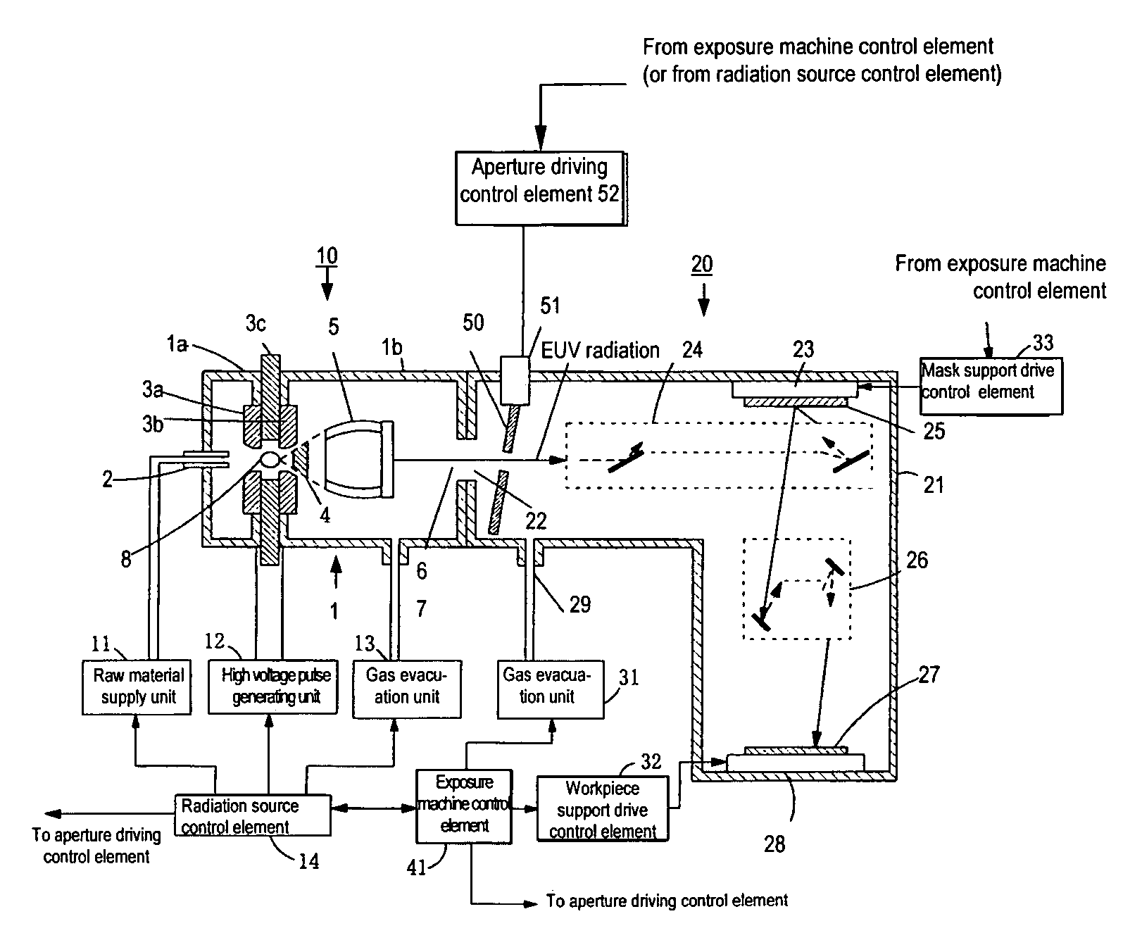
[0129]FIG. 5 shows the arrangement of an embodiment of the EUV exposure tool of the invention. In the embodiment described below, one example of the use of a radiation source device of the DPP type as the radiation source device is shown. However, as was described above, a radiation source device of the LPP type can also be used.

[0130]As is shown in FIG. 5, in this embodiment, the EUV exposure tool, for the most part, comprises a radiation source device 10 and an exposure machine 20. In FIG. 5, the same parts as shown in FIG. 14 are provided with the same reference numbers as in FIG. 14. The action of these parts is also identical to the action of the parts in FIG. 14.

[0131]In a chamber 1, the first main discharge electrode (cathode) 3a and the second main discharge electrode (anode) 3b are arranged such that a ring-like insulating material 3c is clamped by them. Raw material which contains an EUV radiation fuel is supplied to part 1a of the chamber 1 from a raw material supply unit...


PUM


Abstract

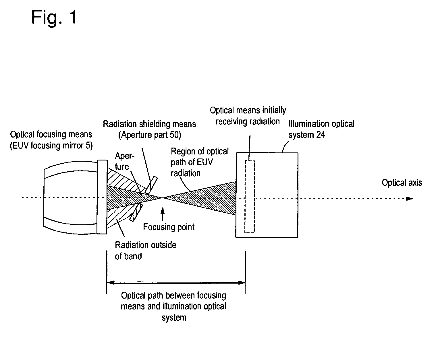
To effectively eliminate radiation outside the band with a wavelength of 13.5 nm which has adverse effects on exposure without reducing the intensity of the EUV radiation with a wavelength of 13.5 nm, in an extreme UV radiation exposure tool which has an extreme UV radiation source device with an EUV focusing mirror which focuses extreme UV radiation and radiation outside the band which is emitted by the high density and high temperature region of a plasma, an illumination optical system for projecting this radiation onto a mask, and a projection optical system which projects the radiation from the mask onto a workpiece, a radiation shield is provided of a size which enables the radiation emerging from the EUV focusing mirror to be completely incident on it, and which has an opening of a size which results in essentially only extreme UV radiation being transmitted through it.

Description

BACKGROUND OF THE INVENTION[0001]1. Field of the Invention[0002]The invention relates to an extreme UV radiation source device with the function of wavelength selection of extreme UV radiation from radiation which is emitted from a plasma. The invention also relates to an extreme UV radiation exposure tool using this extreme UV radiation source device as a radiation source.[0003]2. Description of Related Art[0004]According to the miniaturization and increased integration of an integrated semiconductor circuit, an increase in resolution is required in a projection exposure tool for purposes of its manufacture. To meet this requirement, the wavelengths of the exposure light source are being increasingly shortened. As a semiconductor exposure light source of the next generation in succession to an excimer laser device, an extreme UV radiation source device (hereinafter also called an EUV radiation source device) is being developed which emits EUV radiation (extreme ultraviolet radiatio...

Claims


Application Information

Patent Timeline
Patent Type & Authority Patents(United States)
IPC IPC(8): G21K3/00
CPCB82Y10/00G03F7/70033G03F7/70575G21K5/00
Inventor SEKI, KYOHEI
Owner USHIO DENKI KK
Learn More