
Methods and apparatuses for the development of microstructured nuclear fuels

a nuclear fuel and microstructure technology, applied in the field of nuclear fuels, can solve the problems of high radioactivity of spent fuel assemblies taken from the reactor core, complex uranium or ‘nuclear fuel cycle’, and high so as to reduce the cost of advanced fuel cycle

Active Publication Date: 2009-04-21
THE UNITED STATES AS REPRESENTED BY THE DEPARTMENT OF ENERGY
View PDF6 Cites 26 Cited by
  • Summary
  • Abstract
  • Description
  • Claims
  • Application Information

AI Technical Summary

Benefits of technology

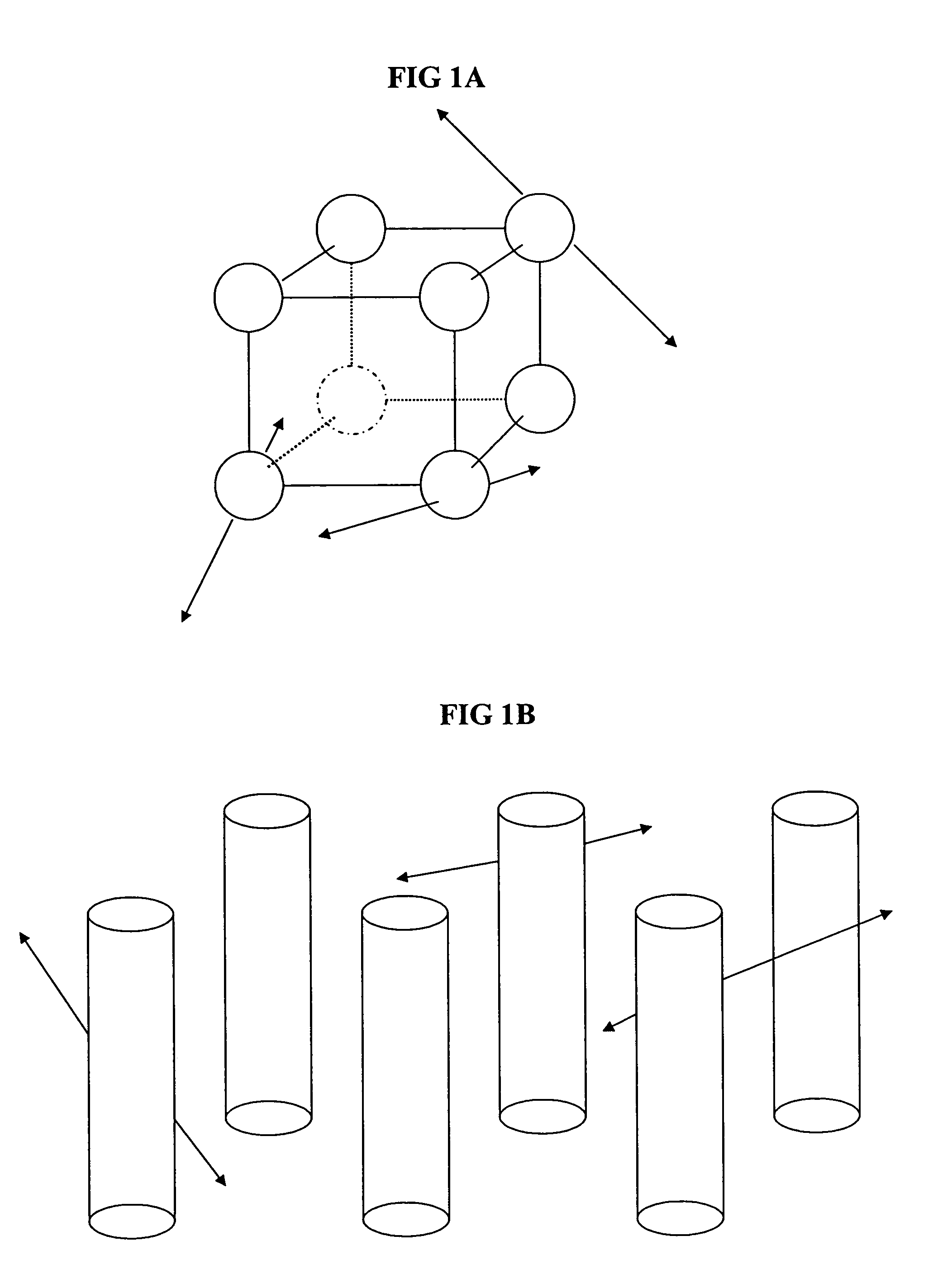
[0007]The present inventors have also found that microstructured nuclear fuels can be manufactured to contain micrometer-sized fissile material structures (e.g., typically in the shape of spheres) spaced uniformly in matrix materials. The advantage of such structures is that they will allow most fission product elements to escape from the fissile material and come to rest in the matrix material.
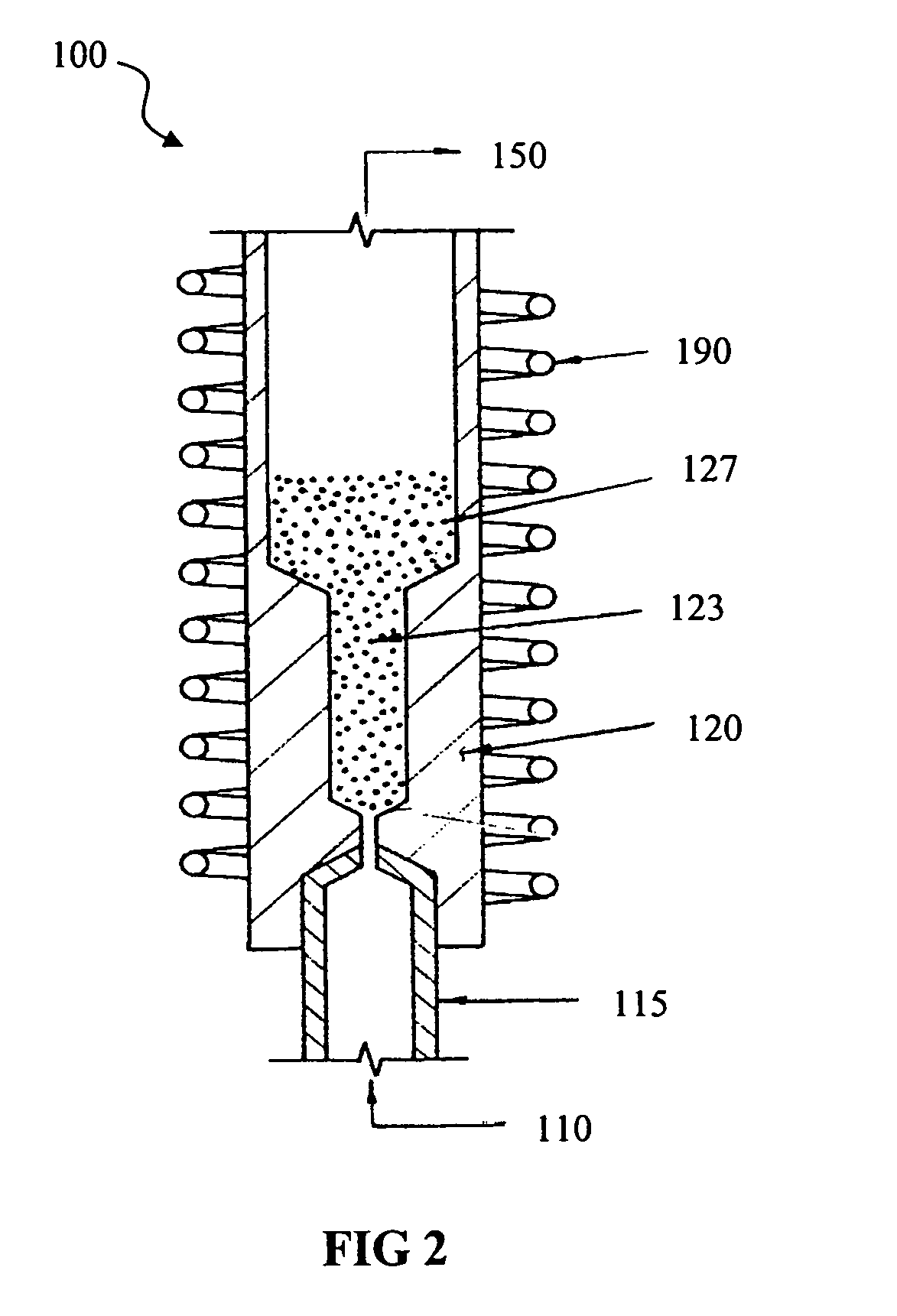
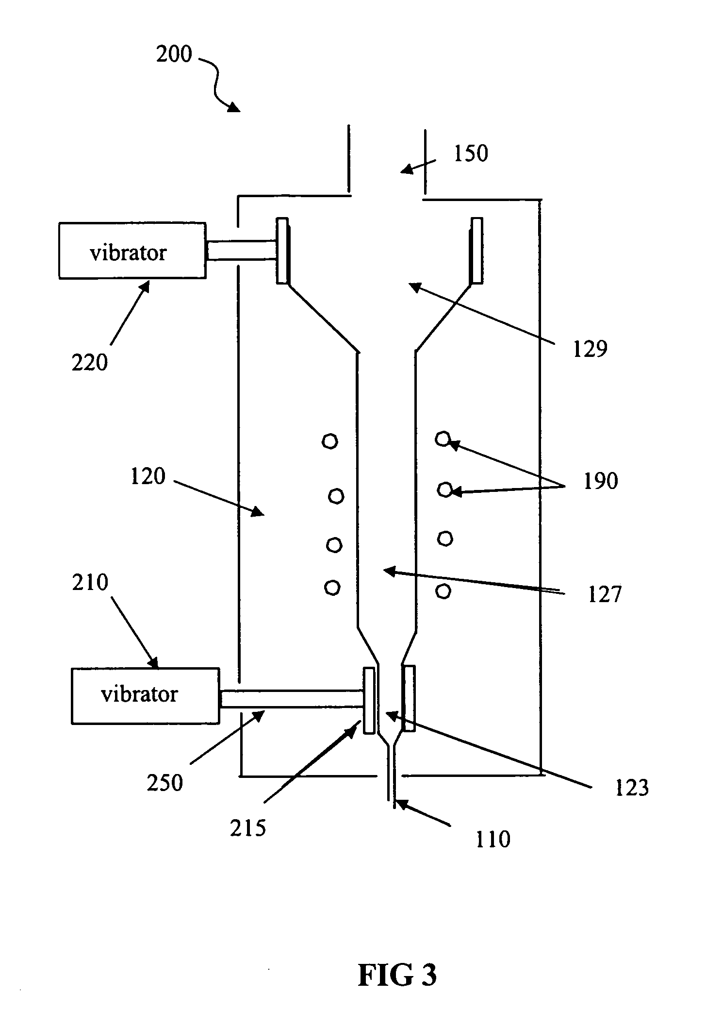
[0010]In accordance with another feature of the present invention, at least one pneumatic and electric vibrator is operationally coupled to the particle coating chamber for causing vibration of the particle coater to promote uniform powder coating within the particle coater during fuel processing.
[0011]In accordance with another feature of the present invention, an exhaust associated with the particle coating chamber can provide a port for placement and removal of particles and powder.
[0013]After a period of use in a nuclear power reactor and subsequent cooling, separation of the fissile material from the matrix containing the embedded fission products will provide an efficient partitioning of the bulk of the fissile material from the fission products. This partitioning process involves processes such as size reduction and separation by density or selective dissolution of the matrix material, e.g., oxidation of a carbon matrix to carbon dioxide or dissolving of a magnesium oxide matrix in alkaline aqueous solution. The fissile material can be reused by incorporating it into new microstructured fuel. The fission products and matrix material can be incorporated into a waste form for disposal or processed to separate valuable components from the fission product mixture.
[0016]In accordance with a feature of the chemical vapor deposition (CVD) reactor, pneumatic and electric vibrators can be provided to promote uniform powder movement and an exhaust.
[0017]Efficient separation of the fissile materials from the fission products using the present invention can greatly reduce costs for an advanced fuel cycle relative to presently used aqueous or proposed pyrochemical separation methods.

Problems solved by technology

Each fuel has its own distinctive fuel cycle; however, the uranium or ‘nuclear fuel cycle’ is more complex than the others.
Spent fuel assemblies taken from the reactor core are highly radioactive and give off a lot of heat.
However, both kinds of storage are intended only as an interim step before the spent fuel is either reprocessed or sent to final disposal.

Method used


Image

  • Methods and apparatuses for the development of microstructured nuclear fuels
  • Methods and apparatuses for the development of microstructured nuclear fuels
  • Methods and apparatuses for the development of microstructured nuclear fuels

Examples


Embodiment Construction

[0026]Referring to FIGS. 1A and 1B, microstructured fuels contain fissile material structures with micrometer-scale dimensions dispersed in a matrix material. Most fission products escape from the fissile material structures and come to rest in the matrix material. This can allow a much cheaper separation of the fission products and fissile material, after the fuel is removed from the power system and allowed to cool for a number of years. FIGS. 1A and 1B is a schematic drawing that illustrates the tracks of fission products (arrows) as they escape from an array of fissile material structures. In FIG. 1A an array of spherical particles of fissile material (e.g., enriched UO2) is pictured with pairs of arrows generally representing the tracks of fission products as they travel out of the fissile particle and eventually come to rest in the surrounding matrix material that separates the spherical particles. In FIG. 1B a cylindrical array of channels filled with fissile material is show...


PUM


Abstract

Microstructured nuclear fuel adapted for nuclear power system use includes fissile material structures of micrometer-scale dimension dispersed in a matrix material. In one method of production, fissile material particles are processed in a chemical vapor deposition (CVD) fluidized-bed reactor including a gas inlet for providing controlled gas flow into a particle coating chamber, a lower bed hot zone region to contain powder, and an upper bed region to enable powder expansion. At least one pneumatic or electric vibrator is operationally coupled to the particle coating chamber for causing vibration of the particle coater to promote uniform powder coating within the particle coater during fuel processing. An exhaust associated with the particle coating chamber and can provide a port for placement and removal of particles and powder. During use of the fuel in a nuclear power reactor, fission products escape from the fissile material structures and come to rest in the matrix material. After a period of use in a nuclear power reactor and subsequent cooling, separation of the fissile material from the matrix containing the embedded fission products will provide an efficient partitioning of the bulk of the fissile material from the fission products. The fissile material can be reused by incorporating it into new microstructured fuel. The fission products and matrix material can be incorporated into a waste form for disposal or processed to separate valuable components from the fission products mixture.

Description

STATEMENT OF GOVERNMENT INTEREST[0001]The United States Government has rights in this invention pursuant to Contract No. W-7405-ENG-36 between the United States Department of Energy and the University of California for the operation of the Los Alamos National Laboratory.FIELD OF THE INVENTION[0002]The present invention is generally related to nuclear fuels. More particularly, the present invention is related to methods and apparatuses for developing microstructured nuclear fuels for advanced nuclear power cycles. Nuclear fuel structures that will allow most fission products to separate from the fissile material during burn-up are also described.BACKGROUND OF THE INVENTION[0003]Like coal, oil and natural gas, uranium is an energy resource that must be processed through a series of steps to produce an efficient fuel for use in the generation of electricity. Each fuel has its own distinctive fuel cycle; however, the uranium or ‘nuclear fuel cycle’ is more complex than the others. To pr...

Claims


Application Information

Patent Timeline
IPC IPC(8): G21C3/02G21C3/58
CPCG21C3/04G21C3/58G21C21/02Y02E30/38Y02E30/30
Inventor JARVINEN, GORDON D.CARROLL, DAVID W.DEVLIN, DAVID J.
Owner THE UNITED STATES AS REPRESENTED BY THE DEPARTMENT OF ENERGY
Learn More