
Soundboard bracing structure system for musical stringed instruments

a soundboard bracing and stringed instrument technology, applied in the field of acoustic musical stringed instruments, can solve the problems of soundboards that are not self-supporting, soundboards placed under stress, and are not able to vibrate uniformly, so as to reduce the deflection of the soundboard, and reduce the effect of soundboard stress

Inactive Publication Date: 2012-04-26
BARILLARO JOSEPH
View PDF1 Cites 9 Cited by
  • Summary
  • Abstract
  • Description
  • Claims
  • Application Information

AI Technical Summary

Benefits of technology

[0046]A secondary objective of the invention is that the primary object is also able and strong enough to alleviate substantially, unwanted deflections of the soundboard, thereby allowing the soundboard to have uniform motion, that's true to its source.
[0048]A fourth objective of the invention is that the primary object is also able; along with using other object bracing means, to further distribute the available vibrating string energy throughout the soundboard surface area, said other bracing object means also thereby allowing for a well-balanced string range response from the soundboard; and along with also providing further object bracing means utilized for producing clear clean rich full musical notes.SUMMARY OF THE INVENTION
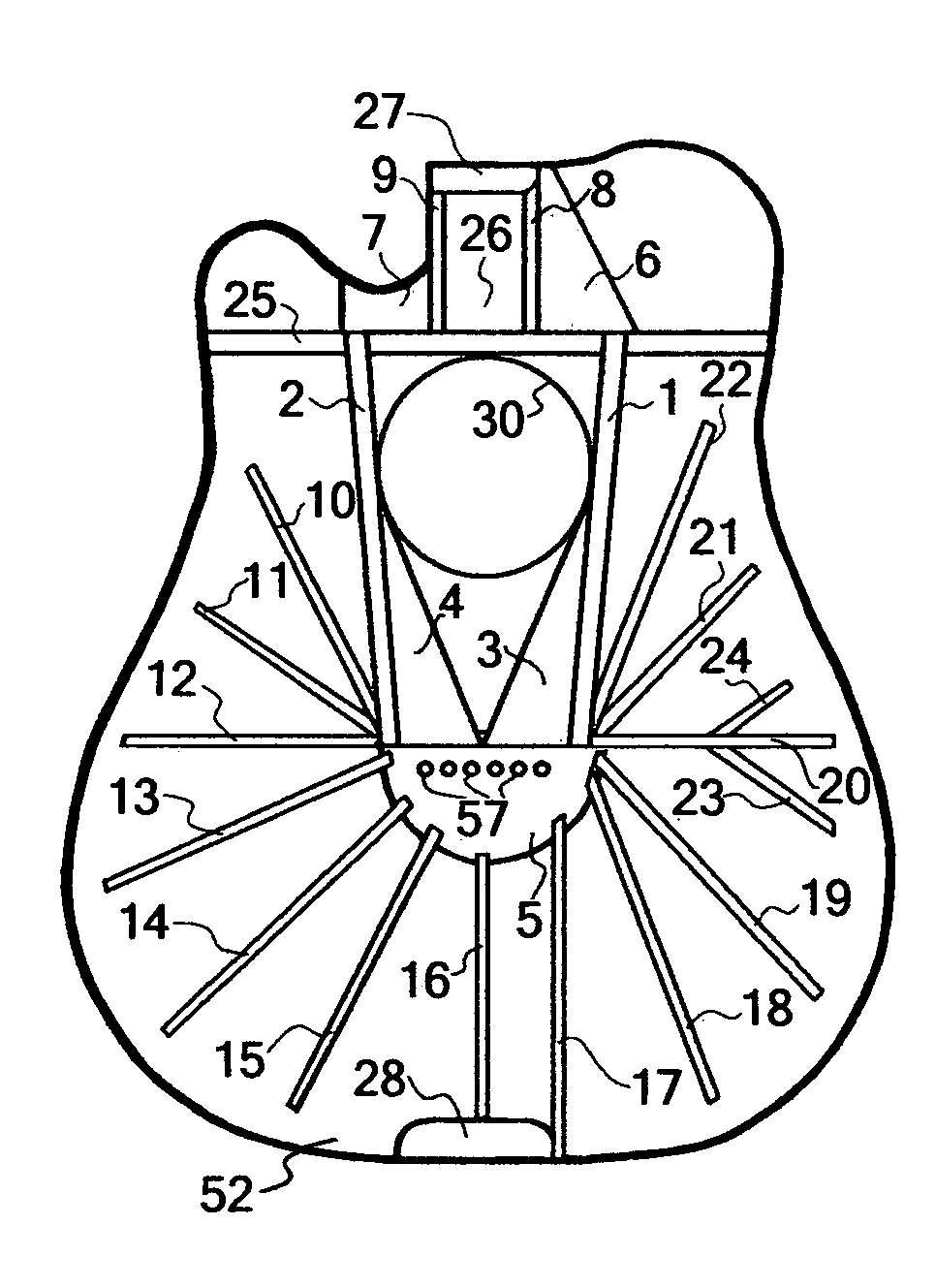
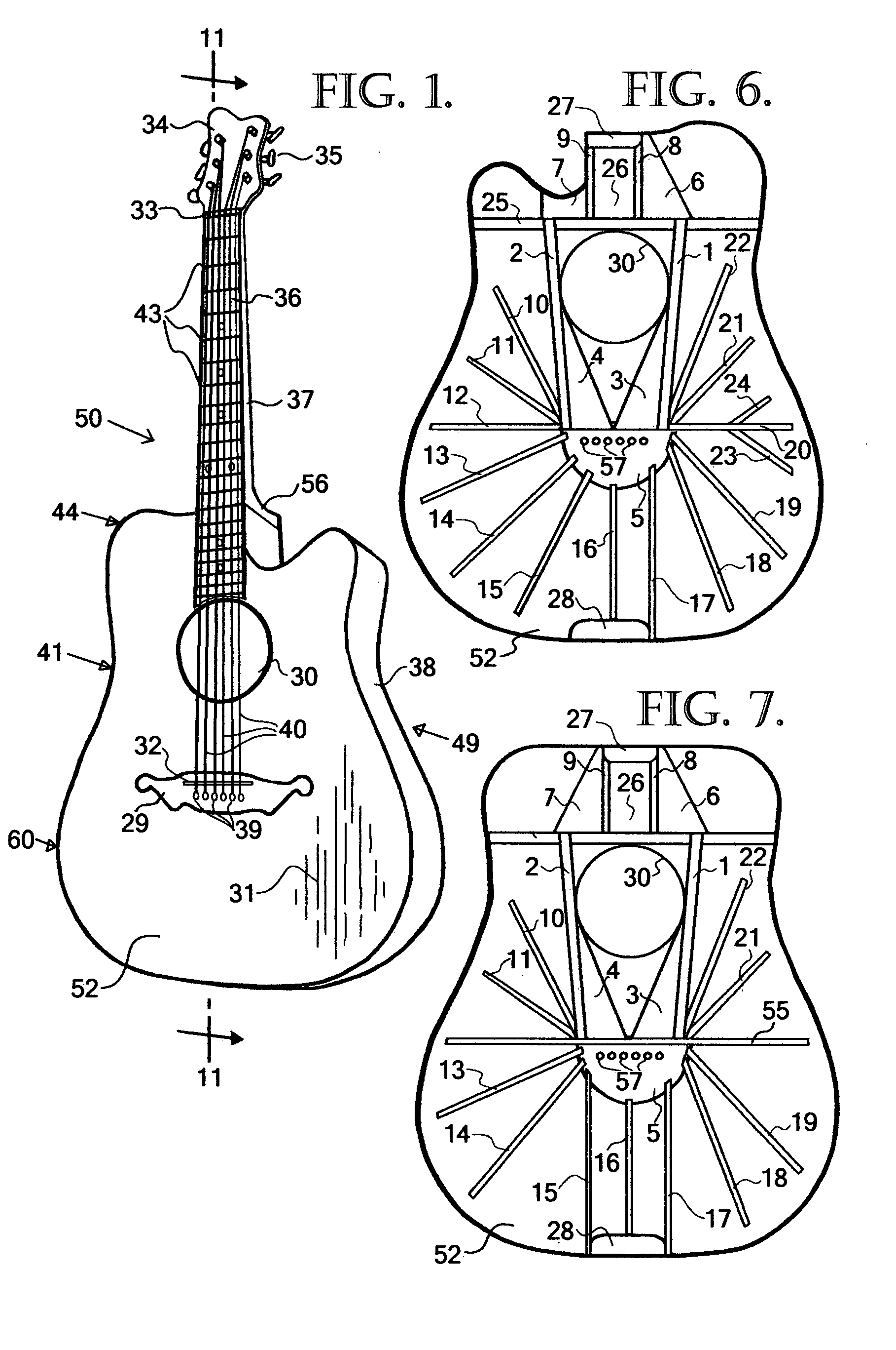
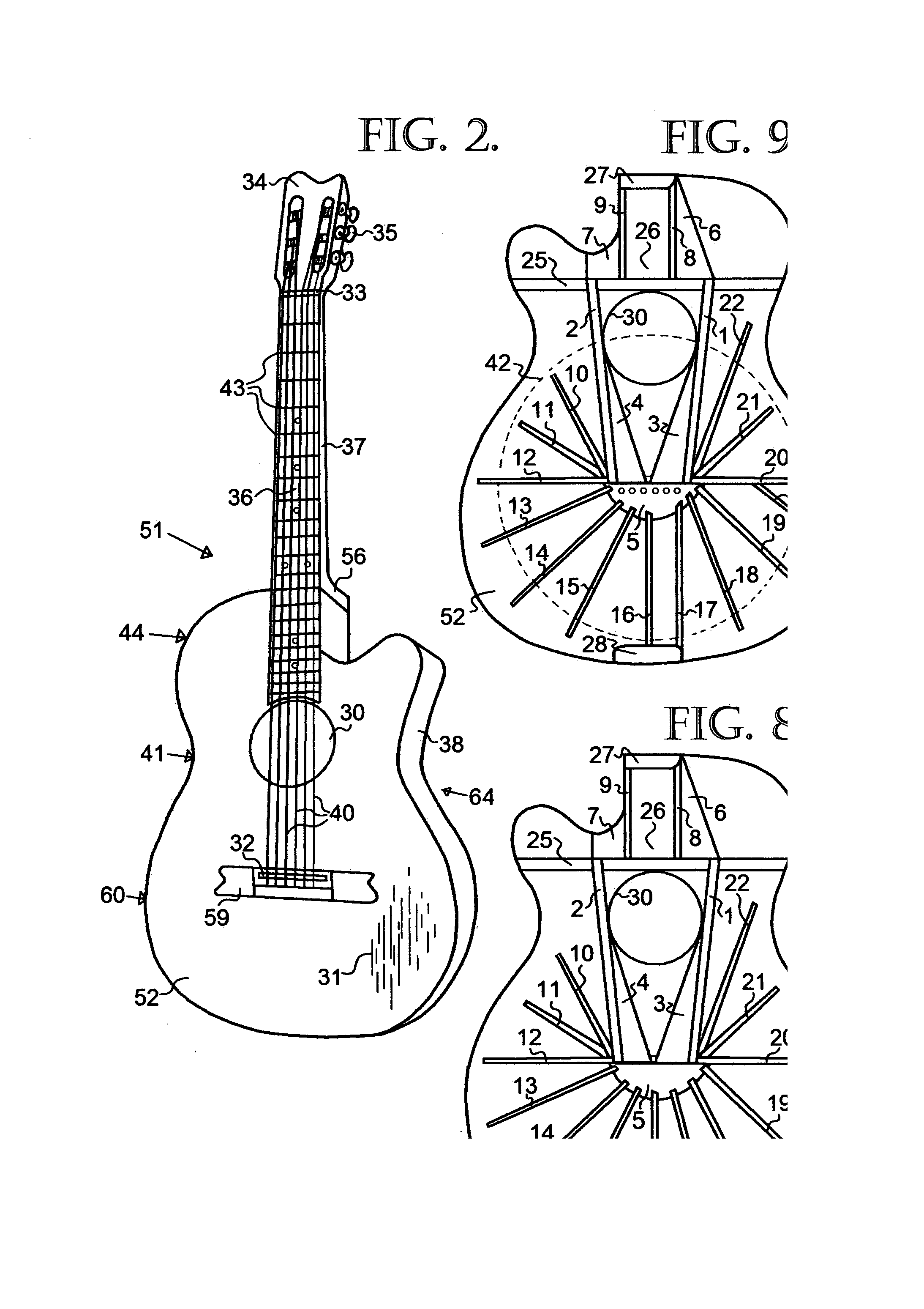
[0051]Two triangular blocks (herein also referred to as “LMBD-blocks”) are used; each with one of their sides positioned in alignment to and directly below the bridge saddle and each with one of their other sides fixed and butted up to one of two longitudinal bar braces. The two longitudinal bar braces (herein also referred to as “indirect-bar” braces) are positioned with each of one of their ends located below either side of the bridge saddle, and to the outside of the string range group span located above, their lengths extend indirectly at an acute angle away from the line of the outermost strings; and where the instrument has a sound hole under the string range group span, running either side of this sound hole continuing above the sound hole with both other ends interconnected to a commonly used transverse brace. The two longitudinal bar braces in combination with the two triangular blocks also serve to support and alleviate substantially unwanted deflections of the soundboard, by upholding the directional predetermined string-length tensions (herein also referred to as “PST”).
[0052]The functions of the triangular blocks are: to firstly load the PST from the attached string range group at the bridge on to the longitudinal bar braces at acute angles to the string lengths, this happens at an acute angle because the two triangular blocks are apart from one another and are largely only supported by the indirect-bar braces; the points (herein also referred to as “points-A”) to where the PST is redirected and loaded on to the indirect-bar braces is to where the PST can be upheld or loaded without failing, these points-A are found basically where the triangular blocks run-out on to the indirect-bar braces and are also the aforementioned third points of reflection taken away and apart from the string line; the indirect-bar braces themselves are also at an opposing obtuse angle to the redirected PST load line. Other functions of the LMBD-blocks are: secondly, the available acoustic energy from two or more vibrating strings will follow the same redirected load lines of PST and in doing so are mixed and concentrated into points-A; thirdly, they serve to buffer inactive strings from being sympathetically vibrated, due to their large mass, allowing for clear clean notes; fourthly, they act to divide and separate the bass string range from the treble string range, by being placed individually there under, effectively creating a separate response for the bass or treble side of the soundboard.
[0053]Points-A are normalized close to the ends (theses “ends” herein also referred to as “points-B”) of the indirect-bar braces interconnecting with the transverse brace. From where the indirect-bar braces interconnect with the transverse brace (points-B) they are well supported, by two blocks (herein also referred to as “reflection-blocks”) adjoining to the above opposite side of the transverse brace and also butt up to a commonly used fingerboard support block. The reflection-blocks serve to efficiently reflect acoustic pressure waves by their large mass, from points-B back through the indirect-bar braces to their opposite ends (theses “ends” herein also referred to as “points-C”) and to the adjoining triangular blocks; where all these bracing parts form a straight line side directly under the bridge saddle and to which a half circular shaped bracing member (herein also referred to as a “transmitting-lobe”) is fixed to. Where then the acoustic pressure waves are distributed throughout the soundboard surface area; since from this location there is no direct support to the PST; firstly by the transmitting-lobe, secondly by the use of long fine bracing bars attached to the transmitting-lobe and extending outwardly in a spoke like pattern towards the near end perimeter of the soundboard, (herein also referred to as “transmitting-bars”). The directional positioning of the transmitting bars towards the perimeter of the soundboard allows for a well balanced string-range response, in regards 330 to sound-levels between the strings and sustain thereof.

Problems solved by technology

Unfortunately the soundboards are not self-supporting and their resistive capabilities towards the tensional forces of the strings are minimal.
The important thing to note is that the side-walls of the body take up some of the string load tension and more importantly the soundboard is placed under stress and is not able to vibrate uniformly due to all the summed up deflections which have been caused by the lack of direct support for the directional load tension of the strings.
Even though this type of guitar normally exhibits only about half of the string tension that is found on steel stringed guitars, the same sorts of problems that are found on the “X” bracing system are also apparent in the “FAN” bracing system.
All of the deflections and deformities are due to the lack of direct support for the strings directional load tension, exerted onto the soundboard via the bridge.
However using a ridged support structure to allow for a prolonged string sustain period; and thereby also alleviating the soundboard from the tensional forces of the strings so that it can also vibrate uniformly; is not a new concept nor is it easily achievable.
All past attempts have adversely affected the instruments tonal qualities and reduced the transmissions of the vibrating strings, into the soundboard.
Central flexing of the rods occurs and is at odds with the vibrating soundboard, putting the soundboard under a damping effect, due to opposing tensions.
Other attempts to support the string tension by locating the through body neck-beam-section closer to the soundboard still have the same problems, even when longitudinal and transverse bracing has been used under the soundboard.
It's also clear that the soundboard is not able to vibrate uniformly due to unwanted soundboard deflections.

Method used


Image

  • Soundboard bracing structure system for musical stringed instruments
  • Soundboard bracing structure system for musical stringed instruments
  • Soundboard bracing structure system for musical stringed instruments

Examples


Embodiment Construction

[0068]While the novel objects, features and advantages, of the inventions well-balanced bracing system structure may be applied to the soundboards of more than one type of an acoustic musical stringed instrument, in order to illustrate and clarify the workings thereof, two examples of an acoustic guitar is used herein.

[0069]Where references to drawings will be made to clarify the method of operations for the embodiments of the guitar examples; but it is to be expressly understood, that the drawings are for the purpose of illustration and description only and are not intended to express the limits of the invention.

[0070]Referring now to FIG. 1, a perspective view of the first guitar examples 50 is of a large body 49 steel stringed acoustic guitar constructed from timber in which the bracing structure system of the invention may be applied to, is shown. The guitar has a hollow body 49 with a waist 41 between curved upper bout 44 and curved bottom bout 60 giving shape to the soundboard...


PUM


Abstract

A bracing structure formed onto the underside soundboard surface of an acoustic musical stringed instrument comprising two bracing bars (1, 2) that are used to support the soundboard and bridge in an indirect fashion from strings directional load tension via a realignment of the strings directional load tension placed through adjoining triangular blocks (3, 4), which re-alignment of the strings directional load tension is taken at acute angles to the line of the strings and focused on a predetermined point found on the bars (1, 2) that are also placed away and at an acute angle to the line of the strings, the acute angling allowing for string vibrations to be largely diverted away from an otherwise direct load line and redirected into the soundboard via a thin half circular shaped block (5) and through several fine bar braces (10, 11, 12, 13, 14, 15, 16, 17, 18, 19, 20, 21, 22, 23, 24) arranged in a somewhat spoke like pattern.

Description

BACKGROUND[0001]1. Technical Field of the Invention[0002]This invention relates to acoustic musical stringed instruments and more particularly to a novel soundboard bracing structure system for improving the quality of the musical sound that is produced by such instruments.[0003]2. Description of Prior Art[0004]Musical stringed instruments such as acoustic—steel or nylon stringed guitars, lutes and the like are typically comprised of a neck attached to a hollow body. The body usually consists of a top face, termed the sound board, to which side walls are formed and attached around its perimeter, the side walls also attach to a backboard, enclosing an air filled chamber. The air filled chamber also referred to as a resonator, can vary in size, shape or form. Traditionally constructed from different timber species but also in recent times using modern materials such as polyester glass reinforced resin or even carbon composites.[0005]The soundboard usually has one or more openings refe...

Claims


Application Information

Patent Timeline
Patent Type & Authority Applications(United States)
IPC IPC(8): G10D3/00
CPCG10D3/02
Inventor BARILLARO, JOSEPH
Owner BARILLARO JOSEPH
Learn More