
Micromechanical component comprising an oscillating body

a micromechanical and oscillating body technology, applied in the direction of optics, measurement devices, instruments, etc., can solve the problems of large lateral dimensions of actuators with large deflection angles, inability to produce large deflection angles, and inability to produce suitable high driving voltages,

Inactive Publication Date: 2003-07-22
FRAUNHOFER GESELLSCHAFT ZUR FOERDERUNG DER ANGEWANDTEN FORSCHUNG EV
View PDF5 Cites 40 Cited by
  • Summary
  • Abstract
  • Description
  • Claims
  • Application Information

AI Technical Summary

Benefits of technology

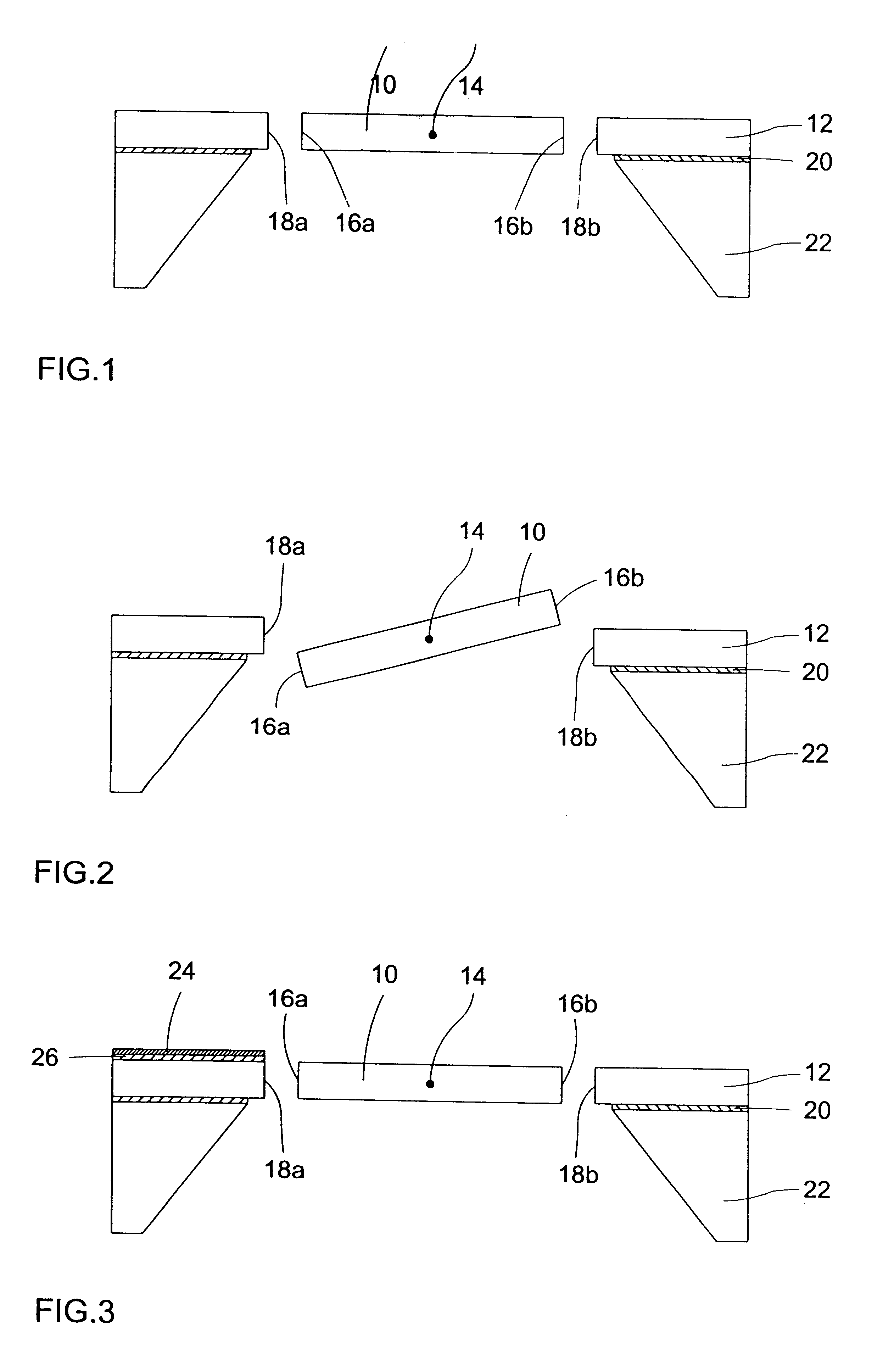
In order to facilitate an oscillation build-up of the oscillating body, asymmetries produced by the manufacturing process or by arranging a further electrode above the counterelectrode may be provided so that a periodic torque causing the oscillating body to oscillate will be generated when an electric voltage having a suitable frequency is applied. The energy which can be coupled in increases as the deflection decreases. When the respective zero passage is detected and when a generator is synchronized therewith, the system is excited at its resonant frequency with the optimum phase position. It follows that, according to the present invention, electrodes restricting the oscillation amplitude due to geometrical reasons can be dispensed with completely. Furthermore, the component according to the present invention can be produced easily making use of known methods in the field of surface mechanics.
It follows that the present invention provides a micromechanical component having a simple structural design and permitting a large deflection of the oscillating body making use of a comparatively low drive voltage. These advantages are achieved according to the present invention, since one or a plurality of lateral surfaces of the oscillating body, which serve as a movable electrode and which are arranged at right angles to the plane of the supporting substrate, co-operate with one or a plurality of inner lateral surfaces of the opening in the frame layer in which the oscillating body is supported so as to permit an oscillation of the oscillating body, an underlying substrate surface, which would restrict the oscillation amplitude, being not required.

Problems solved by technology

Hence, actuators having large lateral dimensions and a large deflection angle cannot be produced.
This approach to a solution entails, however, the disadvantage that suitably high driving voltages are required.
In addition, the separate production of the micromechanical structure and of the supporting plate make the process complicated and expensive.
It is therefore not possible to achieve by means of this set-up a large amplitude making use of low driving voltages.
In the case of this effect, a vertically asymmetric field acts on the movable electrodes and this results in a vertical force which causes the movable electrodes and, consequently, the movable cantilever to move away from the substrate.
Large amplitudes in the case of large lateral dimensions of the movable element can therefore not be achieved in this case either.
The torque that can be realized by the magnetic moment is, however, only low so that even in the case of resonance only amplitudes of less than 3.degree. are achieved.
In addition, the set-up is comparatively complicated and expensive due to the use of a separately manufactured permanent magnet.

Method used


Image

  • Micromechanical component comprising an oscillating body
  • Micromechanical component comprising an oscillating body
  • Micromechanical component comprising an oscillating body

Examples


Embodiment Construction

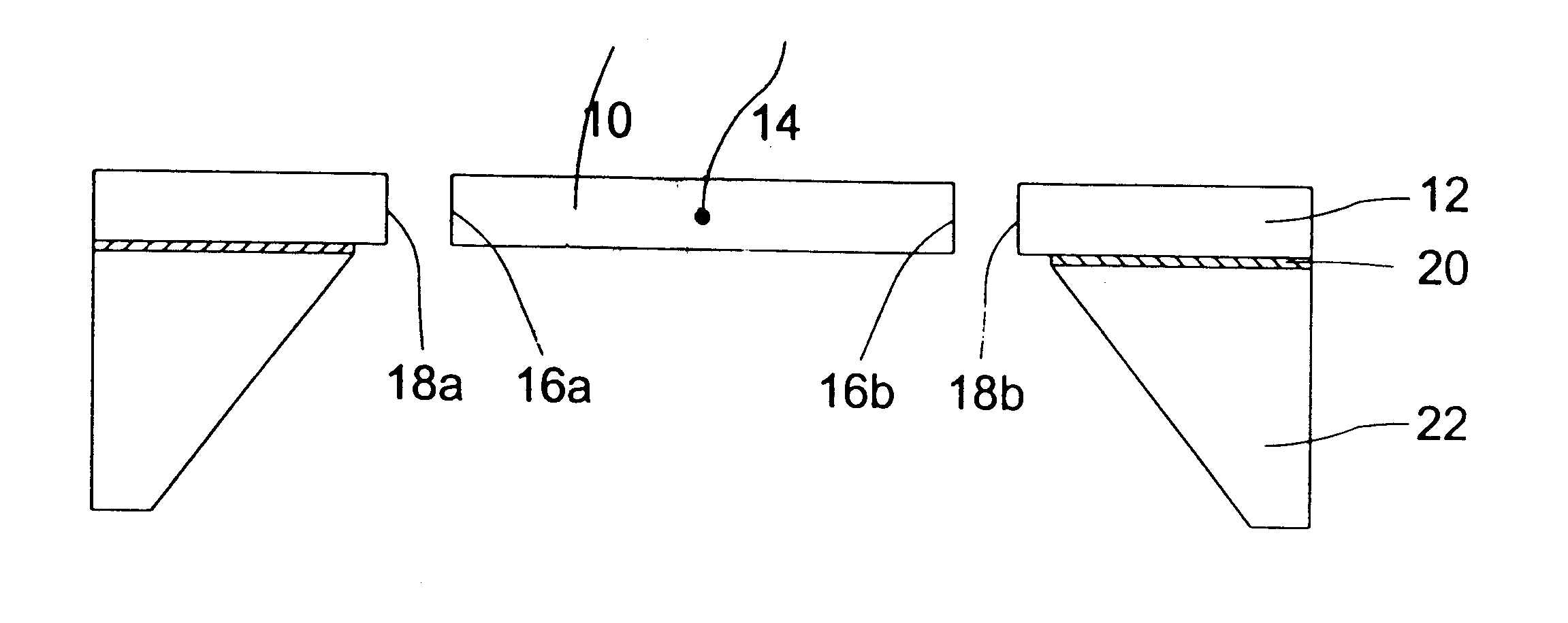
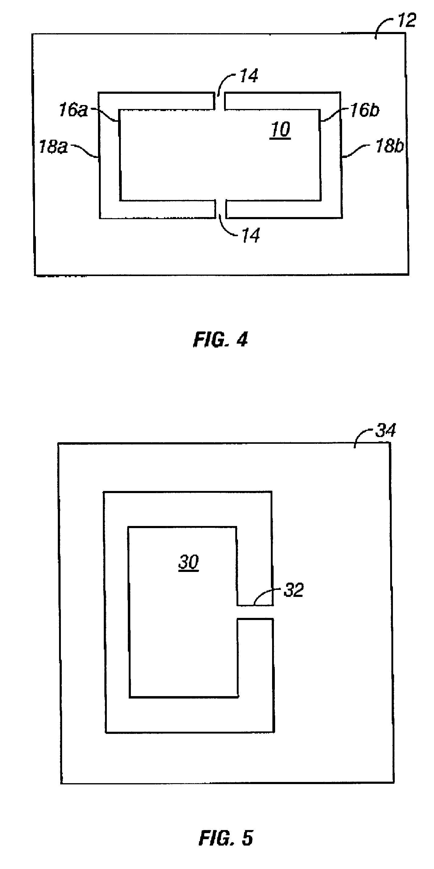
As can be seen from FIG. 1, the micromechanical component according to the present invention comprises an oscillating body 10, a frame layer 12 and a suspension device 14. The oscillating body 10, the frame layer 12 and the suspension device 14 are preferably formed integrally from a silicon layer. This silicon layer is structured such that it is provided with an opening in which the oscillating body 10 is arranged, the oscillating body 10 being supported in the opening by the suspension device 14, which preferably comprises silicon springs structured in the silicon layer. Hence, lateral surfaces 16a and 16b of the oscillating body 10 are arranged in opposed relationship with inner lateral surfaces 18a and 18b of the silicon layer, i.e. the frame layer 12 after the structuring of the silicon layer, in such a way that a kind of plate capacitor is defined therebetween. The suspension device 14, which represents the torsion arms about which the oscillating body 10 can be pivoted, conne...


PUM


Abstract

A micromechanical component comprises a frame layer and an oscillating body which, with the aid of a suspension means, is supported in an opening penetrating the frame layer, in such a way that the oscillating body is adapted to be pivoted about an axis of oscillation vertically to the frame layer plane. At least one oscillating-body lateral surface, which extends substantially at right angles to the frame layer plane, is arranged in relation to at least one inner lateral surface of the opening in such a way that a capacitance formed therebetween is varied by an oscillation of the oscillating body in such a way that an oscillation of the oscillating body about the axis of oscillation can be generated by periodically varying a voltage applied between the frame layer and the oscillating body. A supporting substrate for holding the frame layer is provided, said supporting substrate being implemented such that, in comparison with the influence of the voltage applied between the frame layer and the oscillating body, said supporting substrate has a negligible physical influence on the generation of the oscillation of the oscillating body.

Description

The present invention relates to a micromechanical component comprising a movable portion which can be caused to carry out resonant oscillations, i.e. an oscillating body. In particular, the present invention relates to micromechanical components of such a nature that an oscillation of the oscillating body out of the chip plane, i.e. vertically to the chip plane, is produced.DESCRIPTION OF PRIOR ARTThe functionality of certain micromechanical actuators, e.g. actuators designed to deflect of light, is based on the deflection of a movable element out of the chip plane. The movable element is connected to the rest of the chip via a bending or torsion spring. In order to achieve deflection, it is, on the one hand, known to implement the movable part as an electrode and to use a suitable counterelectrode so that the actuator will be driven by an electric torque. On the other hand, it is known to provide the movable part in the chip plane with conducting tracks in the form of a coil so th...

Claims


Application Information

Patent Timeline
IPC IPC(8): G02B26/08
CPCG02B26/0841
Inventor SCHENK, HARALDDUERR, PETERKUECK, HEINZ
Owner FRAUNHOFER GESELLSCHAFT ZUR FOERDERUNG DER ANGEWANDTEN FORSCHUNG EV
Learn More