
Display device

a technology of display device and display device, which is applied in the field of display device, can solve the problems of low versatility and high cost of printed circuit board with small circular hole, and achieve the effect of low versatility and high cos

Active Publication Date: 2015-11-05
SATURN LICENSING LLC
View PDF3 Cites 41 Cited by
  • Summary
  • Abstract
  • Description
  • Claims
  • Application Information

AI Technical Summary

Benefits of technology

The present patent provides a display unit that reduces the problem of deteriorating display quality over time. The display unit uses a flexible printed circuit board with a small circular hole, which has limitations in versatility and high cost. The curvature of the second plate-like member is designed to be equal to or smaller than the first plate-like member, which reduces nonuniform deflection in the wiring section and allows for suppression of stress on the wiring section. This results in a more stable display performance.

Problems solved by technology

However, such a flexible printed circuit board with a small circular hole has issues of low versatility and high cost.

Method used


Image

  • Display device
  • Display device
  • Display device

Examples


modification example 1 (

2. Modification Example 1 (Example in which a control circuit board is partitioned)

3. Modification Example 2 (Example in which a liquid crystal panel and a control circuit board are arranged nearly on a plane)

embodiment

1. Embodiment

1-1. Configuration of Main Part

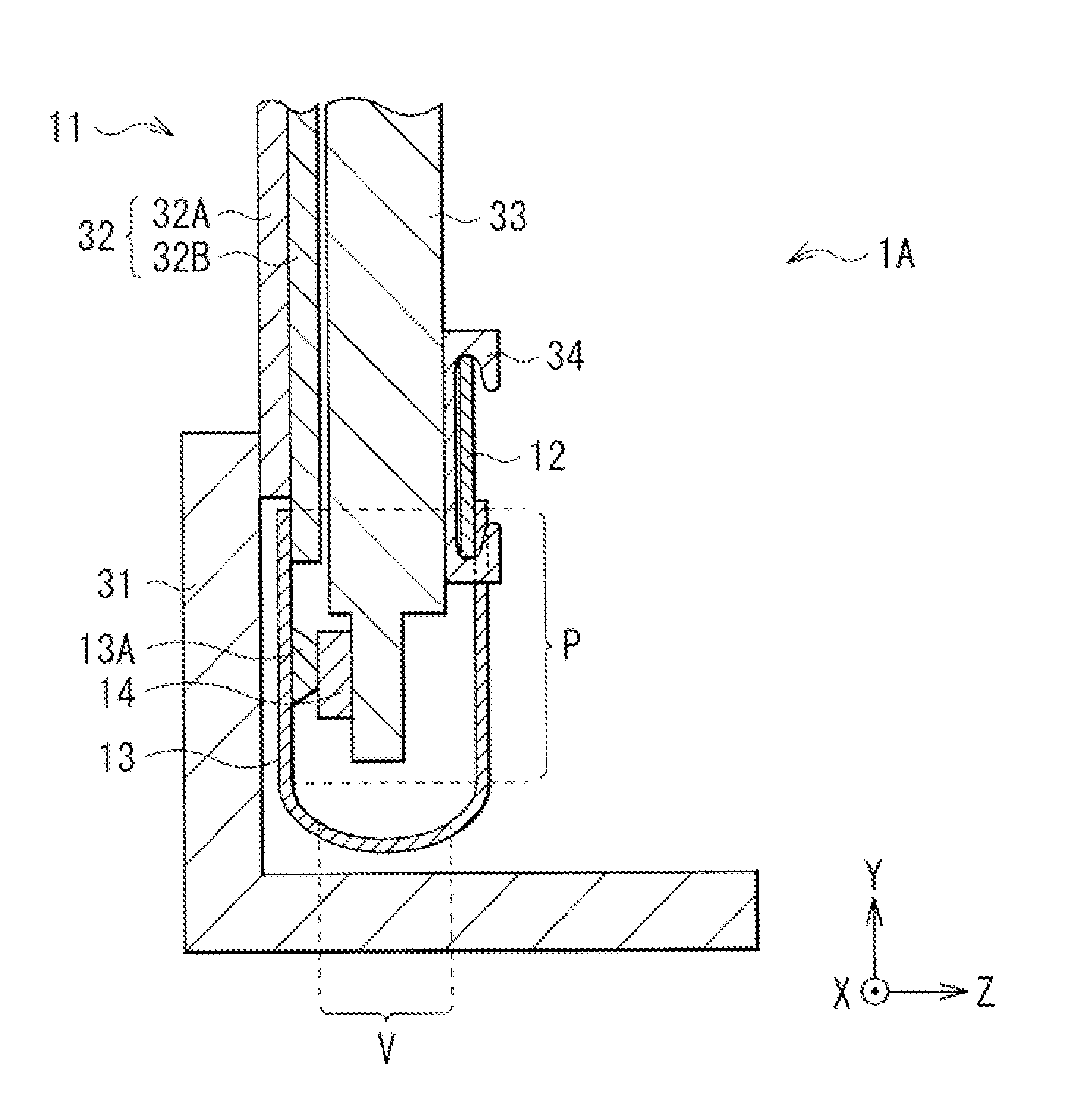
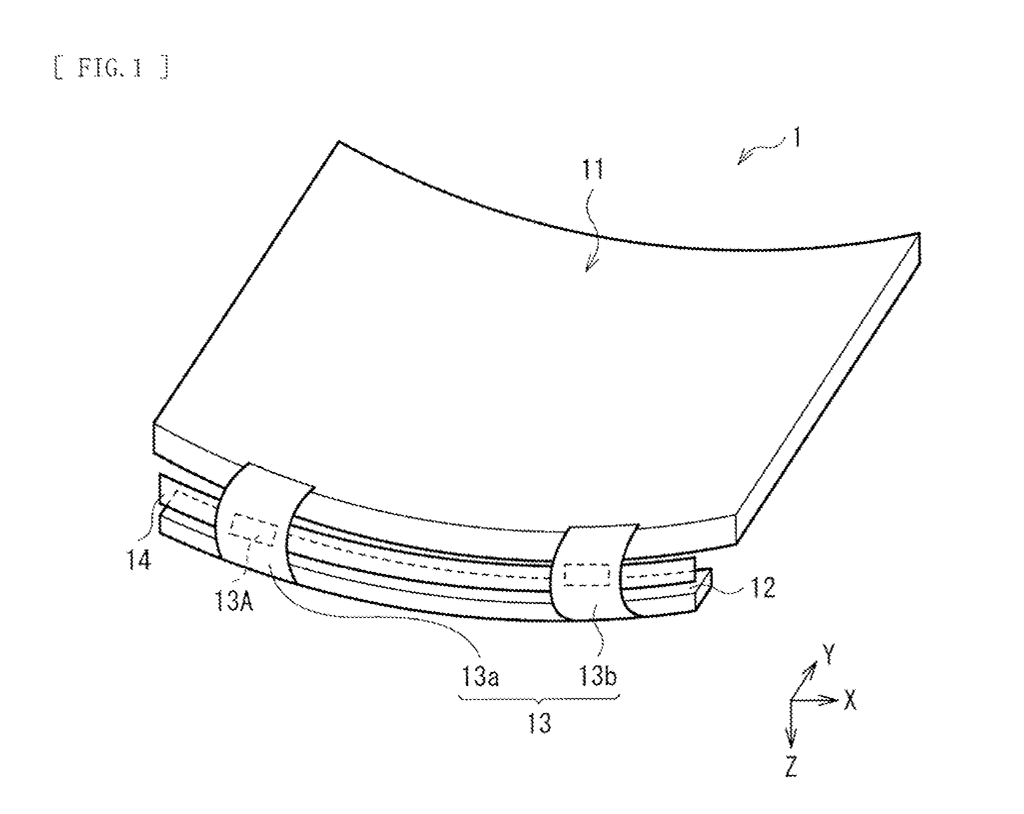
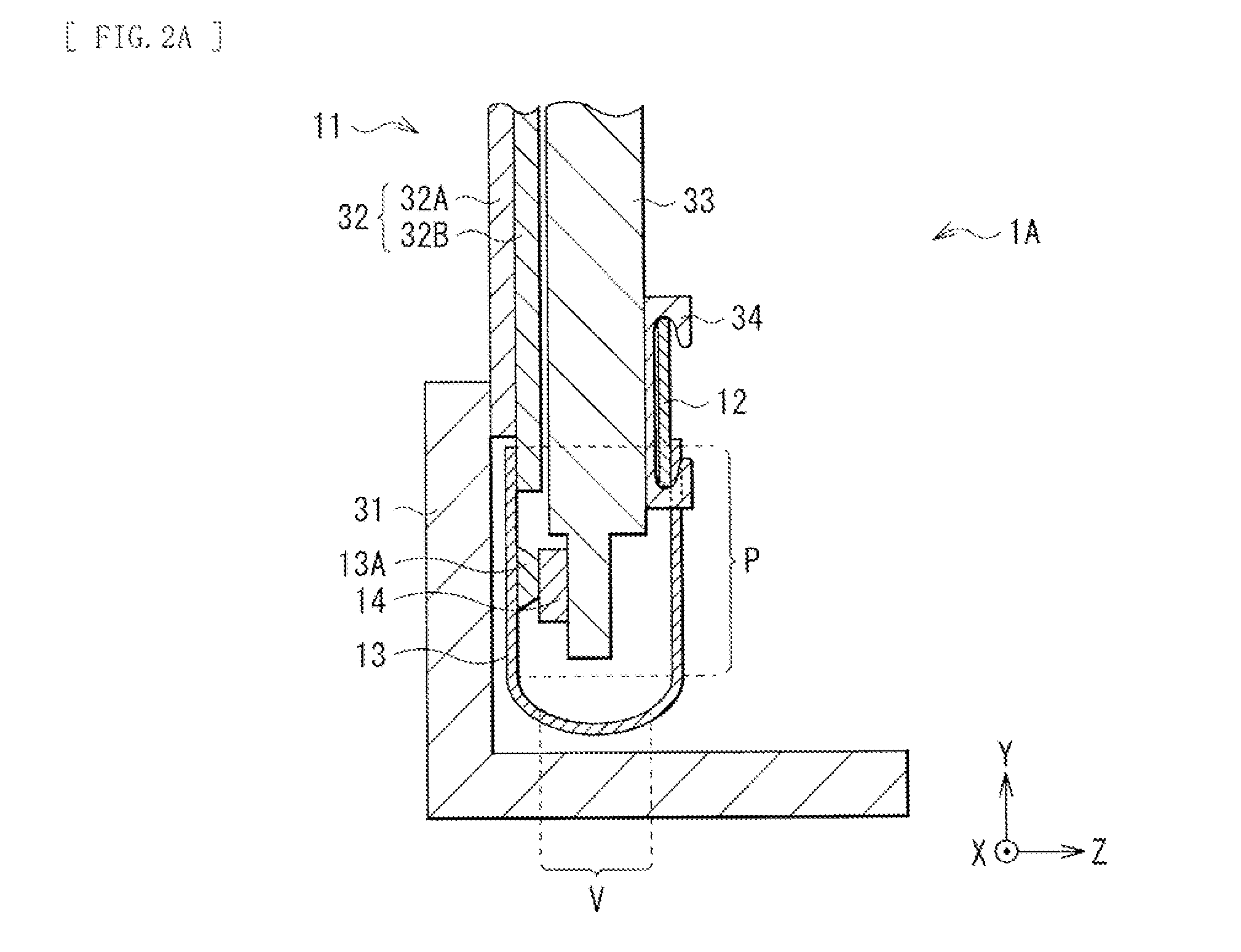
[0032]FIG. 1 illustrates an example of a configuration of a main part of a display unit (a display unit 1) according to an embodiment of the present disclosure. The display unit 1 may include, for example, a liquid crystal panel 11 (corresponding to a first plate-like member) as a display body. The liquid crystal panel 11 is curved in an arc shape in a one-dimensional direction (an X direction in this case), and is connected to a control circuit board 12 (corresponding to a second plate-like member) through, for example, a COF (Chip On Film) 13 (corresponding to a wiring section) having flexibility. As will be described in detail later, the control circuit board 12 is curved in an arc shape on a one-dimensional direction (the X direction) in a similar manner to the liquid crystal panel 11, and a curvature of the control circuit board 12 may be preferably larger than 0 and equal to or smaller than a curvature of the liquid crystal panel 11....

modification example 1

[0072]FIG. 12 illustrates a configuration of a main part of a display unit 2 according to Modification Example 1 viewed from directly above. This display unit 2 differs from the above-described display unit 1 in that the control circuit board 12 is partitioned (into two along the X direction in this case).

[0073]In a case where the display unit 2 is large, the control circuit board 12 extends in a curve direction (the X direction in this case). When the control circuit board 12 is too long, in the driving state of the display unit (a state in which temperature is higher than that before driving of the display unit), the control circuit board 12 extends largely, thereby applying stress to the COF 13; therefore, this is not preferable. In such a case, the control circuit board 12 is partitioned into a plurality of portions as with this Modification Example 1 to reduce a length in an extending direction of one control circuit board 12. It is to be noted that the length of the control ci...


PUM


Abstract

A display unit of the present disclosure includes: a first plate-like member including a display device; a second plate-like member including a drive circuit, the drive circuit configured to control the display device; and one or two or more wiring sections having flexibility, the wiring sections configured to connect the first plate-like member and the second plate-like member to each other, in which a curvature of the second plate-like member is larger than 0 and equal to or smaller than a curvature of the first plate-like member.

Description

TECHNICAL FIELD[0001]The present disclosure relates to a display unit suitable for a large-screen television or the like.BACKGROUND ART[0002]As flat panel type display units, liquid crystal display units, plasma display units, electroluminescence units, and the like are known, and the liquid crystal display units have spread widely as a representative of the flat panel type display units. In recent years, these flat panel type display units have been growing in size, and demand for displaying on a curved surface has been growing in terms of a sense of spread and designability.[0003]In a case where the above-described flat panel type display unit performs display on a curved surface, i.e., in a case where a display panel is curved and deformed in an arc shape, the following issue arises. For example, with respect to the display panel that is curved and deformed in an arc shape, a control circuit board provided with a drive circuit configured to control driving of the display panel ha...

Claims


Application Information

Patent Timeline
IPC IPC(8): G02F1/1345G02F1/1333H05B44/00
CPCG02F1/133382G02F1/13452G02F1/1333G02F1/133305H10K59/131H10K2102/311
Inventor SHIBAHARA, SEIJI
Owner SATURN LICENSING LLC
Learn More