
Real-time simulation combined modeling method for power electronic elements based on FPGA

A technology of real-time simulation and electronic components, applied in the direction of electrical digital data processing, special data processing applications, instruments, etc., can solve the problems of lack of simulation models, affecting the processing speed of simulator power electronic components, etc.

Active Publication Date: 2017-05-10
STATE GRID TIANJIN ELECTRIC POWER +1
View PDF2 Cites 14 Cited by
  • Summary
  • Abstract
  • Description
  • Claims
  • Application Information

AI Technical Summary

Problems solved by technology

[0018] At present, some researchers have conducted research on FPGA-based real-time simulation of power systems. Although the combination of high-performance FPGAs and small-step switching models is very suitable for real-time simulation of power systems, the number of power electronic components has become a new issue. The problem
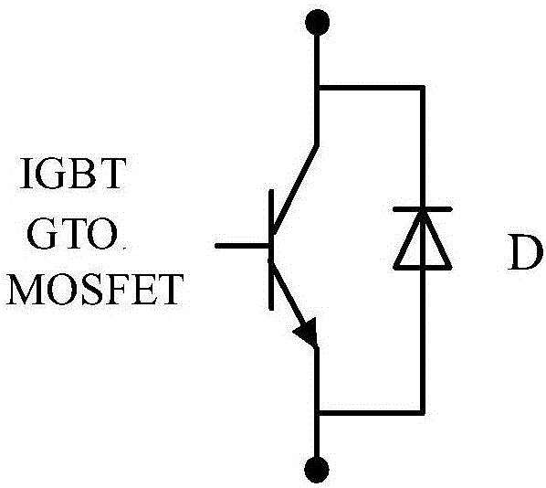
At this stage, a large number of controllable power electronic components, such as IGBT, GTO, MOSFET, etc., are mostly anti-parallel freewheeling diodes D in application, which makes only one IGBT full-controlled converter contain 12 power electronic components. When the simulation scale is large When the number of power electronic components is large, the number of power electronic components will further increase, which seriously affects the processing speed of the simulator for power electronic components; at the same time, there are many types of power electronic devices and their connection methods in different applications, and there is a lack of unified simulation Model

Method used


Image

  • Real-time simulation combined modeling method for power electronic elements based on FPGA
  • Real-time simulation combined modeling method for power electronic elements based on FPGA
  • Real-time simulation combined modeling method for power electronic elements based on FPGA

Examples


Embodiment Construction

[0050] The FPGA-based real-time simulation combined modeling method for power electronic components provided by the present invention will be described in detail below in conjunction with the accompanying drawings and specific embodiments.

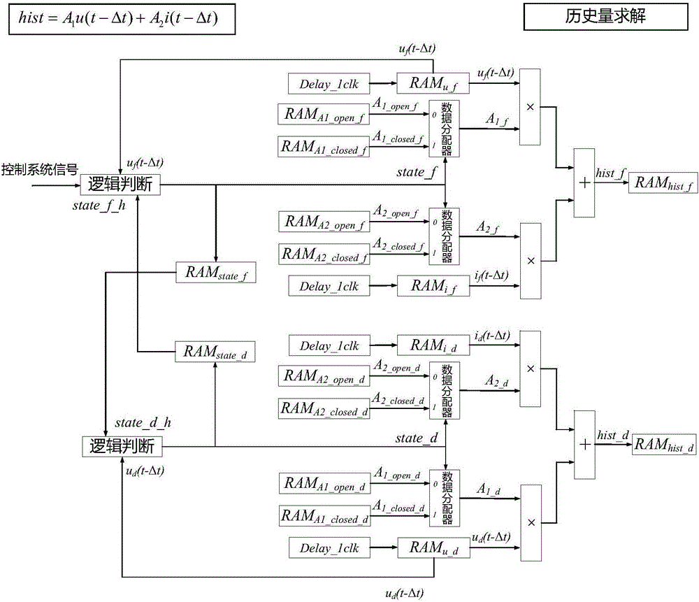
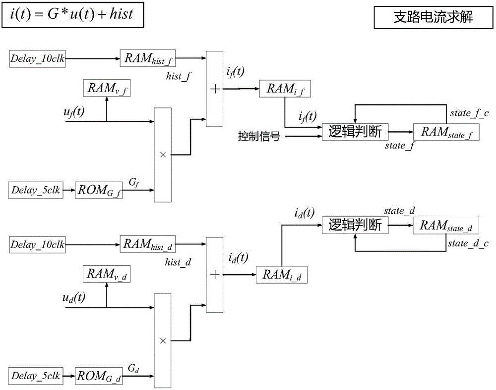
[0051] Such as Figure 4 As shown, the FPGA-based power electronic component real-time simulation combined modeling method provided by the present invention includes the following steps carried out in order:

[0052] Step 1: In the offline environment, use the basic components of the electrical system to model the power system, and read the basic parameter information and topological connection relationship of basic passive components, line components, power components, circuit breaker components, and power electronic components. According to the overall solution framework of the electrical system in the real-time simulator, the processing methods of the above-mentioned various basic components and the matrix solution method, calculate the...


PUM


Abstract

A real-time simulation combined modeling method for power electronic elements based on FPGA is disclosed, which comprises the steps of carrying out modeling, setting the length of real-time simulation steps, establishing combined models, uploading parameters, carrying out simulation, judging condition, calculating historical quantity, calculating voltages, calculating electric currents and judging simulation time. In the offline environment, modeling is carried out on the electric power system by utilizing basic elements of the electrical system. The length of the real-time simulation steps of the electrical system is set for delta t. The combined models are established through the parallel circuit which consists of switching devices and diodes. The parameters are uploaded to the online simulation environment. The simulation starts to be carried out in the online environment. The condition of the switching devices and the diodes is judged. The historical quantity of the switching devices and the diodes is calculated. The voltage of every node is calculated. The electric currents of step branches at the moment of the switching devices and the diodes are calculated. The simulation time whether reaches simulation or not is judged. Single elements can be made by the established models which can carry out combined modeling by utilizing various controllable power electronic devices and the diodes. The real-time simulation combined modeling method for power electronic elements based on FPGA has the advantages of improving the universal property of the power electronic elements modeling, reducing the number of the power electronic elements effectively and improving the processing speed of the power electronic elements in the real-time simulation under the premise of guaranteeing simulation accuracy.

Description

technical field [0001] The invention belongs to the technical field of computer control, in particular to an FPGA-based real-time simulation combined modeling method for power electronic components. Background technique [0002] With the interconnection of regional power grids, the scale of modern power systems continues to expand. High-power power electronic equipment such as high-voltage direct current transmission and FACTS are widely used in power transmission systems. The introduction of clean energy such as renewable energy power generation and distributed power supplies will also With the promotion of power electronic equipment in the distribution network, the components of the power system are becoming more and more complex, and the interweaving of dynamic characteristics at different time scales has become the main feature of the modern power system. Therefore, new challenges have been proposed for the power system simulation technology. The research on the operatin...

Claims


Application Information

Patent Timeline
Patent Type & Authority Applications(China)
IPC IPC(8): G06F17/50
CPCG06F30/331
Inventor 丁承第宣文博闫大威周进雷铮王魁李媛媛梁群毛华刘树勇宋佳王世举
Owner STATE GRID TIANJIN ELECTRIC POWER
Learn More