High pressure fuel pump provided with damper

a technology of high-pressure fuel pump and damper, which is applied in the direction of fuel injecting pump, machine/engine, positive displacement liquid engine, etc., to achieve the effect of improving stability, reducing the cost of operation and maintenance, and improving the capacity of absorbing pulsation

Inactive Publication Date: 2009-04-07
HITACHI AUTOMATIVE SYST ENG +1
View PDF37 Cites 40 Cited by
  • Summary
  • Abstract
  • Description
  • Claims
  • Application Information

AI Technical Summary

Benefits of technology

[0007]It is an object of the present invention to provide a fuel feed system capable of feeding fuel into a fuel injection valve at a fuel pressure with improved stability.
[0009]By this configuration, it is made possible to feed fuel to a fuel injection valve at a fuel pressure with improved stability. Moreover, it is possible to adjust the lift of the damper against the external pressure. Thereby, it is possible to provide a mechanism having a higher capacity of absorbing pulsation without upsizing. Thus, it becomes possible to feed fuel to a fuel injection valve at a fuel pressure with improved stability.

Problems solved by technology

That is, when a single diaphragm is used as a mechanism to reduce fuel pressure pulsation, it becomes necessary to make the diaphragm large-sized to sufficiently suppress the pulsation because it has a low capacity of reducing fuel pressure pulsation.

Method used


Image

  • High pressure fuel pump provided with damper
  • High pressure fuel pump provided with damper
  • High pressure fuel pump provided with damper

Examples


embodiment 1

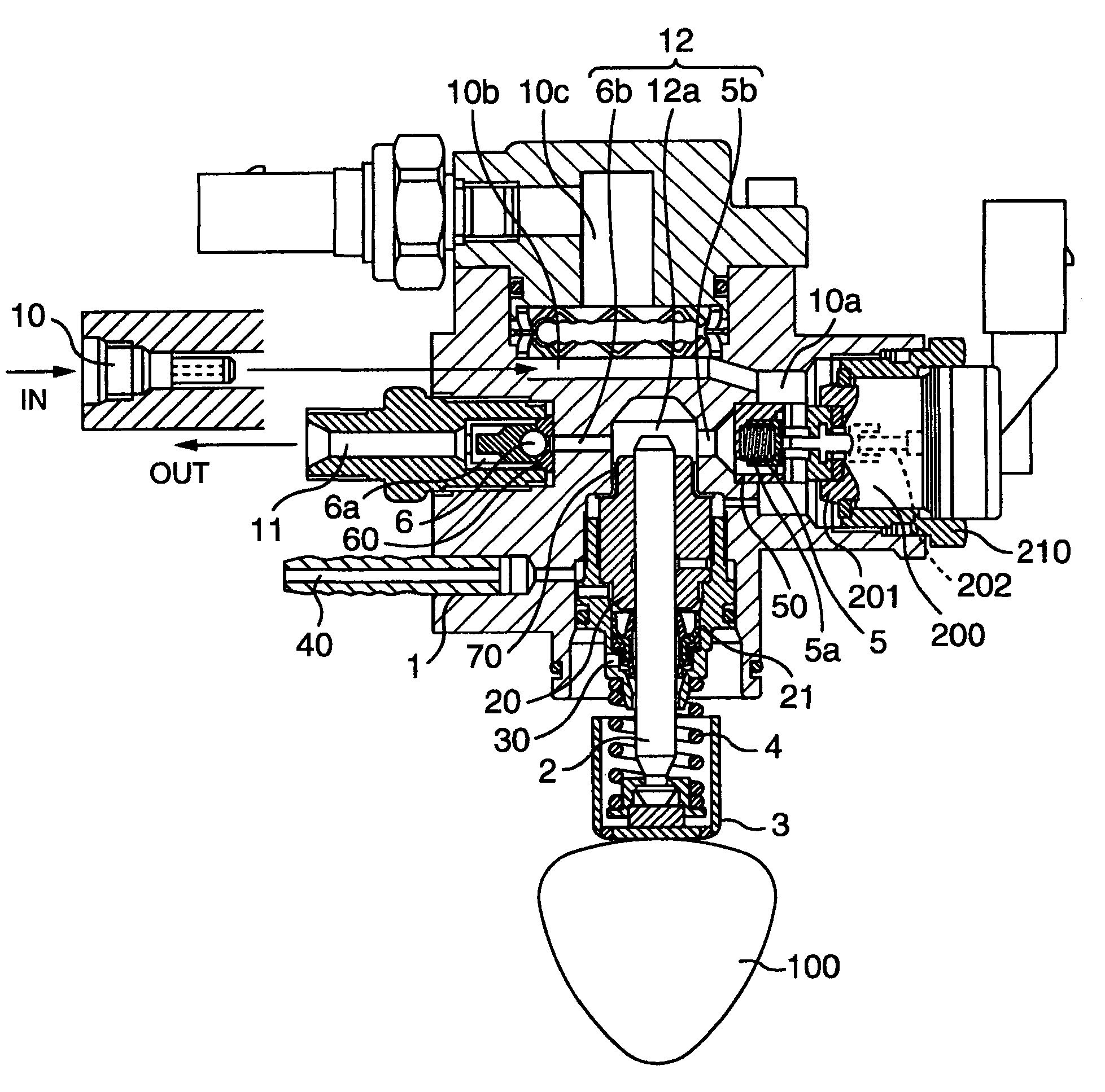
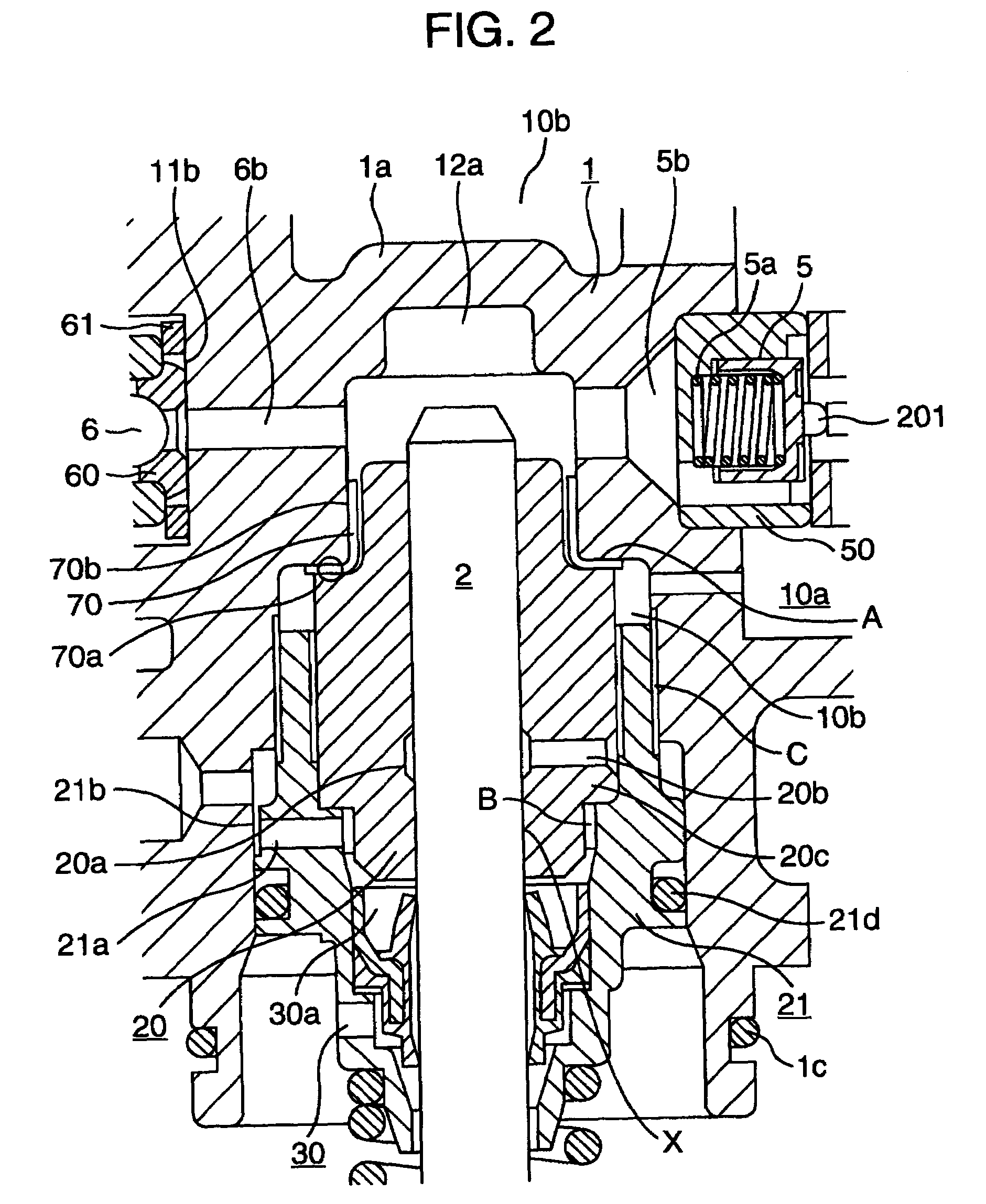
[0027]Referring to FIGS. 1 to 3, a basic configuration and operation of a high-pressure fuel pump according to an embodiment will be described. FIG. 1 is a vertical sectional view of an entire pump; FIG. 2 is an enlarged view of an interior of the pump in FIG. 1; and FIG. 3 shows a configuration of a fuel injection system.

[0028]A pump body 1 is formed with a fuel inlet passage 10, a discharge passage 11, and a pressurizing chamber 12. The inlet passage 10 and the discharge passage 11 are provided with an intake valve 5 and a discharge valve 6 respectively; each of which is held being urged in one direction by a spring 5a and a spring 6a respectively thereby acting as a check-valve to limit the direction of the fuel flow. The pressurizing chamber 12 is formed of a pump chamber 12 through which a pressurizing member, or a plunger 2 slides, an inlet 5b in communication with the intake valve 5, and an outlet 6b in communication with the discharge valve 6.

[0029]Further, in an inlet chamb...

embodiment 2

[0069]Next, another embodiment will be described referring to FIGS. 10, 11.

[0070]FIG. 10 shows a configuration in which the mechanism for reducing fuel pressure pulsation shown in FIG. 3 is placed in the low-pressure fuel passage upstream from the high-pressure fuel feed pump.

[0071]This configuration allows the low pressure pulsation of the fuel to be fed under pressure to the high-pressure fuel feed pump to be effectively reduced by means of a compact, low-cost damper, thereby making it possible to achieve a fuel feed system having a high-pressure fuel feed pump with the capability of stable discharge.

[0072]FIG. 11 shows a configuration in which the mechanism for reducing fuel pressure pulsation shown in FIG. 3 is placed in the high-pressure fuel passage downstream from the high-pressure fuel feed pump.

[0073]This configuration allows the pulsation of high-pressure fuel to be effectively reduced with a compact, low-cost damper, thereby making it possible to achieve a fuel feed syste...

embodiment 3

[0075]Now still another embodiment will be described. In FIG. 13, there is shown a fuel feed system for an internal combustion engine comprising a fuel tank 50 and a low-pressure pump 51 for feeding the fuel in the fuel tank to a fuel injection valve, wherein a mechanism 80 for reducing fuel pressure pulsation is provided and secured with a cover, and a fuel chamber is provided inside the cover.

[0076]This configuration allows the mechanism for reducing fuel pressure pulsation to be secured with a simple structure, making it possible to achieve a compact and low-cost fuel feed system.

[0077]According to the embodiment described so far, forming the above described diaphragm type damper for a fuel feed system of a metal allows the durability of the diaphragm to be enhanced, making it possible to achieve a fuel feed system composing of a damper having a wide range of working fuel pressure.

[0078]Also, in a fuel feed system for an internal combustion engine including a fuel tank and a low-...


PUM


Abstract

A fuel feed system capable of feeding a fuel to fuel injection valves at a fuel pressure with improved stability is provided. A fuel feed system for an internal combustion engine including a fuel tank and a low-pressure pump for feeding the fuel in the fuel tank to fuel injection valves, is provided with a diaphragm type damper having a wave-shape cross section at a position in contact with the fuel. Also, in a high-pressure fuel feed pump including a pressurizing chamber for pressurizing the fuel, a plunger for pumping the fuel within the pressurizing chamber, an intake valve provided at a fuel inlet of the pressurizing chamber, a discharge valve provided at a fuel outlet of the pressurizing chamber, and a low-pressure chamber provided in an upstream of the intake valve, a mechanism for reducing fuel pressure pulsation is disposed in a space of the low-pressure chamber provided in the upstream of the intake valve, and a fuel pressure sensor for measuring the fuel pressure is mounted near the mechanism for reducing fuel pressure pulsation.

Description

REFERENCE TO RELATED APPLICATIONS[0001]This application is a continuation of U.S. application Ser. No. 10 / 274,034, filed Oct. 21, 2002, which claims priority to Japanese Patent Application No. 2002-057132, the entire disclosure of which is incorporated herein by reference.BACKGROUND OF THE INVENTION[0002]The present invention relates to a fuel feed system for feeding fuel for fuel injection valves of an internal combustion engine.[0003]Regarding such a fuel feed system, mechanisms utilizing a single diaphragm to reduce fuel pressure pulsation are disclosed in JP-A-2001-55961, JP-A-2001-59466, JP-A-2000-297725, JP-A-2000-266183, JP-A-2000-265926, JP-A-2000-249019, JP-A-2000-193186, and Japanese patent No. 3180948.[0004]Moreover, methods utilizing a metal bellows as the mechanism to reduce fuel pressure pulsation are disclosed in JP-A-2001-82290 and JP-A-2001-59466.[0005]Furthermore, methods utilizing a rubber diaphragm as the mechanism to reduce fuel pressure pulsation are disclosed ...

Claims


Application Information

Patent Timeline
Patent Type & Authority Patents(United States)
IPC IPC(8): F02M59/46F02D33/00F02M37/00F02M55/00F02M55/02F02M55/04F02M59/36F02M59/44F02M63/00F02M63/02F04B11/00F04B49/24
CPCF02M37/0041F02M55/04F02M59/366F02M59/44F02M63/0225F04B11/0016F04B49/243F02D33/003F02M37/0047F02M63/0001F02M2200/04F02M2200/24F02M2200/315F04B2205/01F04B2205/02F04B2205/05F02M2200/247
Inventor USUI, SATOSHIODAKURA, HIROSHIONOSE, TORUSAITO, ATSUJIABE, MASAMIYAMADA, HIROYUKI
Owner HITACHI AUTOMATIVE SYST ENG
Why Eureka
Try Eureka