
Dynamic micro speaker with dual suspension

a dynamic, micro-speaker technology, applied in the direction of diaphragm construction, loudspeaker diaphragm shape, electrical transducer, etc., can solve the problems of weakened damping capability of vibration system, inability to use the parts employed in such general speakers, and large eccentric vibration of conventional micro-speakers, etc., to achieve small and ultra-slim structure, prevent the disconnection of wires, and wideband reproduction

Inactive Publication Date: 2009-03-17
JY CUSTOM CO LTD
View PDF16 Cites 27 Cited by
  • Summary
  • Abstract
  • Description
  • Claims
  • Application Information

AI Technical Summary

Benefits of technology

"The present invention provides a micro-speaker with a second suspension made of highly resilient material, which enables wideband reproduction and low distortion of bass sounds in a very small and ultra slim structure. The second suspension is a highly resilient and conductive leaf spring that is connected to the voice coil and the vibration plate. The second suspension can have a symmetrical shape and can be connected to the signal-supplying portion through a spring terminal connection. The suspension section has damping diaphragms to perform functions of electrically collecting and damping vertical vibration. The suspension section can have two damping diaphragms to provide more stable support points. The protruding portion of the second suspension is fixed to the frame to ensure stable connection."

Problems solved by technology

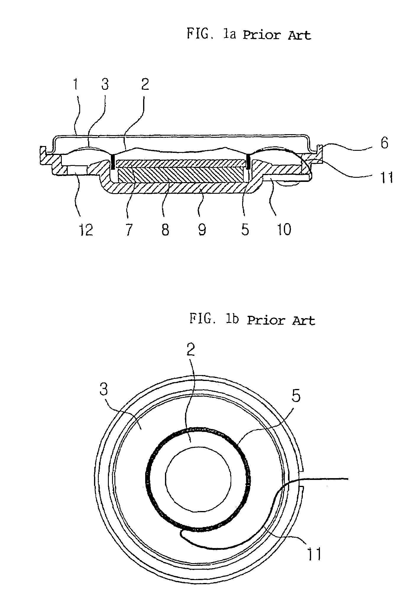
However, as for micro-speakers that are mainly used in near sound fields and employed in products with very limited spaces for accommodating speakers, including cellular phones, notebook computers and camcorders, it is impossible to use the parts employed in such general speakers, i.e. additional copper foils and silk wires, due to very narrow spaces that will be occupied by parts.
For this reason, compared with conventional large infinity speakers, the conventional micro-speaker is subjected to the occurrence of a large amplitude of eccentric vibration accompanied with abnormal sounds throughout the vibration plate since the damping capability of the vibration system is weakened as electrical energy input into the vibration system is increased.
Further, since the electric power is supplied through two strands of the residual wire of the voice coil mainly composed of copper, considerable progressive damage naturally occurs as the vibration of the vibration system becomes excessive.
This means that as the input energy increases, a distortion phenomenon of reproduced sounds accordingly becomes severer and there is a high possibility of the occurrence of progressive disconnection of the wire.
For this reason, substantial increases in the distortion and the possibility of the occurrence of disconnection of the wire become much higher.
If the limit frequency of reproduction of bass sounds in a single unit of such a conventional micro-speaker of 17 mm in size which employs a processing method using a single suspension and a voice coil is required to be 400 Hz in consideration of some degree of lingering sounds and a balance of reproduction ranges, the aforementioned problems such as disconnection of the wire and abnormal sounds occur considerably.
As a result, reproduced sounds become very small sounds.
Thus, the conventional micro-speakers have already exhibited vulnerability and limitation due to an inverse correlation between the reproduced sound quality and the allowable input power.
Therefore, it cannot be expected to remarkably improve the function of such conventional micro-speakers.
However, in view of the aforementioned external features of the very small and ultra slim structure of the existing micro-speakers, it is impossible for the micro-speakers to employ an additional suspension or silk wires as vibration adaptive, electrical signal-transmitting bodies, which are made of cotton or synthesized fiber and then woven and thermally molded and are included in general infinity speakers.

Method used


Image

  • Dynamic micro speaker with dual suspension
  • Dynamic micro speaker with dual suspension
  • Dynamic micro speaker with dual suspension

Examples


Embodiment Construction

[0026]Hereinafter, preferred embodiments of the present invention will be described in detail with reference to the accompanying drawings.

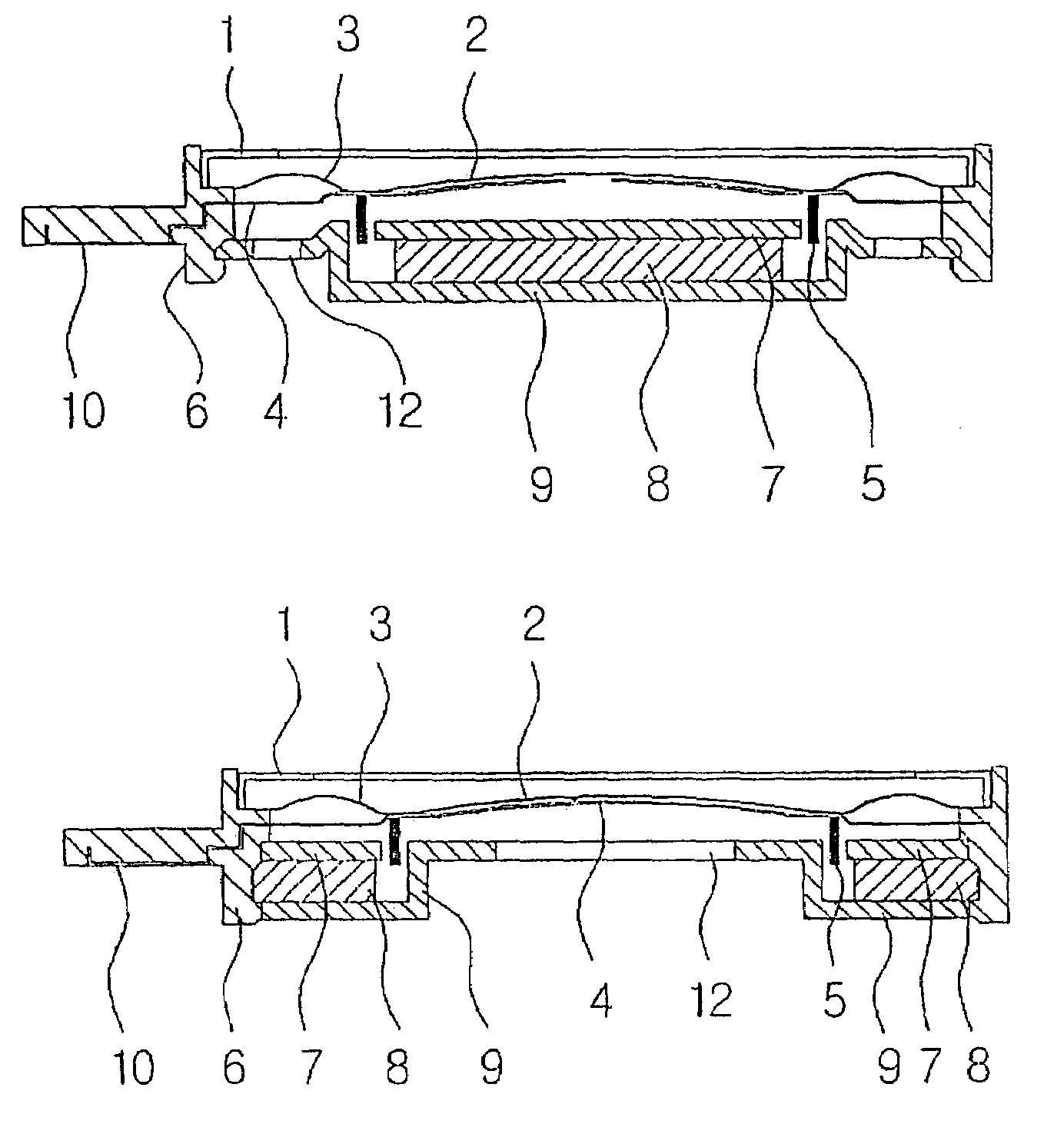
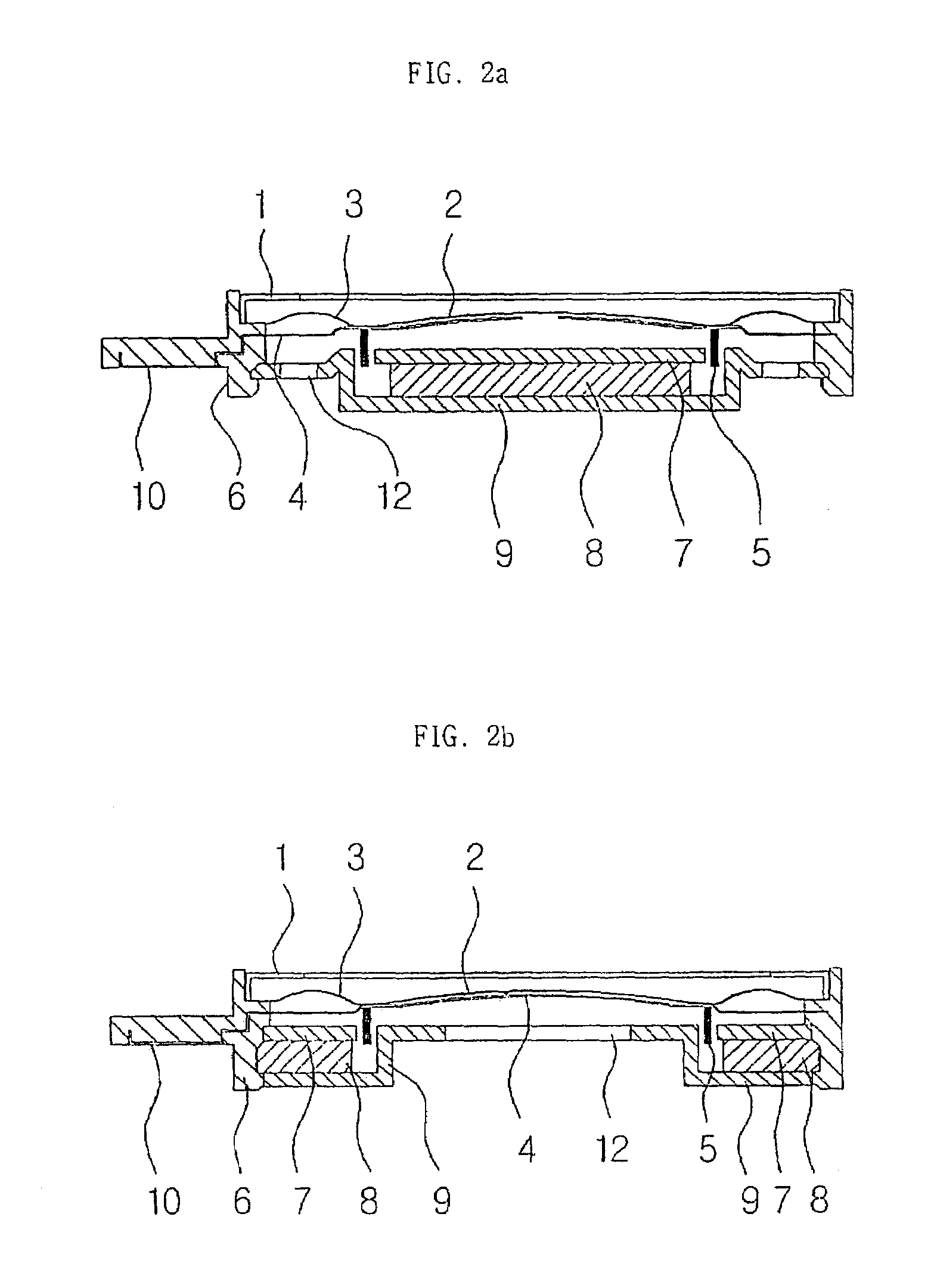
[0027]FIG. 2a shows a sectional view of an internal magnet-type dynamic micro-speaker according to the present invention.

[0028]Elements of the micro-speaker according to the present invention similar to those of the conventional micro-speaker are denoted by like reference numerals in the drawings, and their corresponding functions are also identical with each another.

[0029]The main feature of the micro-speaker according to the present invention is the provision of a second suspension 4 comprising a spring (including a leaf spring) made of highly resilient material, and the attachment of a voice coil 5 to a lower surface of the second suspension 4. It is preferred that the second suspension 4 be formed to conform to the shape of the micro-speaker in section. An outer periphery (edge) of the second suspension 4 is fitted into and fixedly seated in a...


PUM


Abstract

The invention relates to a micro-speaker with a second suspension made of highly resilient material installed inside of the speaker. The speaker is able to provide high level acoustic output with low distortion rate in a wide frequency range with a very small and slim structure and it may prevent a disconnection of a lead connecting the voice coil and the electrode. The speaker includes a yoke, a permanent magnet, a plate, a vibration plate integrated with a first suspension, a voice coil, a frame and a protector. The speaker further comprises a second suspension made of highly resilient material installed between the plate and the vibration plate, and is characterized in that the voice coil is attached to the lower surface of the second suspension and the vibration plate is attached to the upper surface of the second suspension and the vibration plate is attached to the upper surface of the second suspension and the outer periphery of the second suspension is fixed to the frame.

Description

TECHNICAL FIELD[0001]The present invention relates to a micro speaker for use in reproducing sounds through micro electronic equipment (e.g., cellular phones, camcorders, PDAs, digital cameras, notebook computers, LCD TVs, DVDs and the like), and more particularly, to a highly reliable, dynamic micro-speaker that is provided with an additional conductive second suspension into which an excessive vibration-damping function and an electrical signal-transmitting function are incorporated to enable wideband reproduction of high level acoustic output and low distortion while maintaining the speaker in a very small and ultra slim structure.BACKGROUND ART[0002]Conventional electro-acoustic transducers can be roughly classified into speaker systems comprising a combination of functional units in charge of reproduction in specific frequency ranges such as low, middle and high frequency ranges; general speakers of which a single unit can perform reproduction in entire frequency ranges; micro-...

Claims


Application Information

Patent Timeline
Patent Type & Authority Patents(United States)
IPC IPC(8): H04R1/00H04R9/02H01R4/48H04R1/02H04R1/06H04R7/12H04R7/20H04R9/06
CPCH04R1/06H04R7/20H04R9/043H01R4/4809H04R1/025H04R7/18H04R9/06H04R2307/201H04R2307/207H04R2499/11H04R1/02
Inventor YOO, OK-JUNG
Owner JY CUSTOM CO LTD
Learn More