
Reduced parallel and pipelined high-order MIMO LMMSE receiver architecture

a receiver architecture and high-order technology, applied in the field of receivers, can solve the problems of low reliability of the algorithm of option (i), unstable algorithms, and high hardware implementation costs, and achieve the effect of reducing the number and complexity of conventional ffts design modules

Active Publication Date: 2009-02-17
VIVO MOBILE COMM CO LTD
View PDF6 Cites 12 Cited by
  • Summary
  • Abstract
  • Description
  • Claims
  • Application Information

AI Technical Summary

Benefits of technology

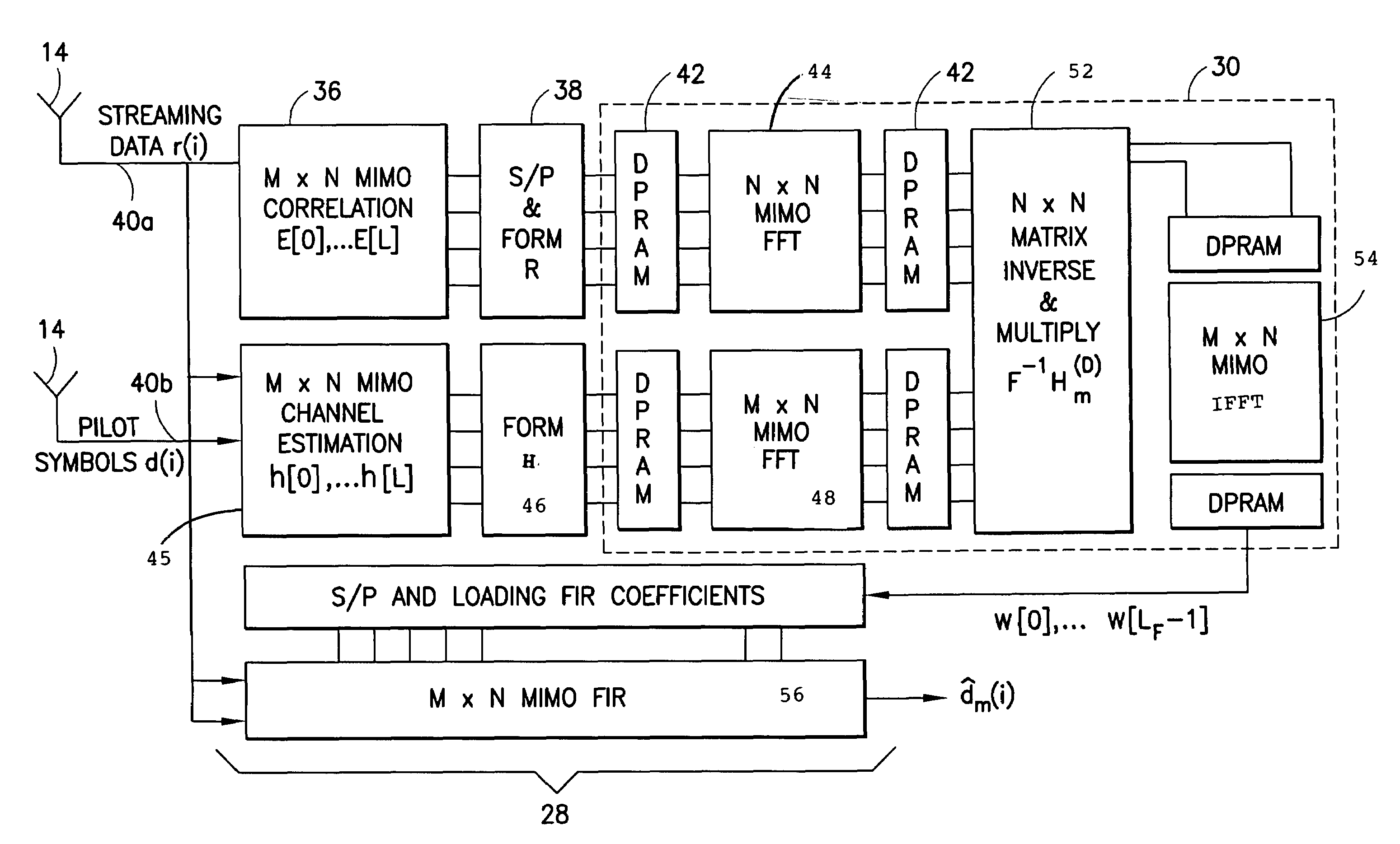
[0010]This invention is a method and LMMSE receiver for restoring spreading code orthogonality in a multipath channel signal. An inverse of an overall NF×NF matrix of the prior art is avoided by inverting several sub-matrices of size N×N, where N is the number of receive antennas and F is the channel length parameter. The number and complexity of conventional FFTs design modules is reduced with Hermitian optimization and tree pruning, and the inverse of the sub-matrices are further simplified.
[0015]Other aspects of the invention include streamlining the calculation processing, parallelizing the calculations for the various filter coefficients, and pipelining the various parameters in time to reduce data path lengths and eliminate repeat calculations.

Problems solved by technology

With a very short spreading gain, the conventional Rake receiver could not provide acceptable performance.
This is very expensive for hardware implementation.
The algorithms of option (i) suffer from stability problems because the convergence depends on the choice of good step size (see M. J. Heikkila, K. Ruotsalainen and J. Lilleberg, “SPACE-TIME EQUALIZATION USING CONJUGATE-GRADIENT ALGORITHM IN WCDMA DOWNLINK”, IEEE Proceeding in PIMRC, pp.
For a MIMO receiver with high dimension, the complexity of a MIMO receiver increases dramatically with the number of antennas.

Method used


Image

  • Reduced parallel and pipelined high-order MIMO LMMSE receiver architecture
  • Reduced parallel and pipelined high-order MIMO LMMSE receiver architecture
  • Reduced parallel and pipelined high-order MIMO LMMSE receiver architecture

Examples


Embodiment Construction

[0027]The following acronyms are used herein:[0028]LMMSE: Linear Minimum Mean Squared Error;[0029]CDMA: Code-Division Multiple Access;[0030]SIMO: Single Input Multiple Output;[0031]MIMO: Multiple Input Multiple Output;[0032]FPGA: Field Programmable Gate Array;[0033]VLSI: Very Large Scale Integrated circuit;[0034]ASIC: Application Specific Integrated Circuit;[0035]RTL: Register Transfer Layer;[0036]DSP: Digital Signal Processing;[0037]FFT: Fast Fourier Transform

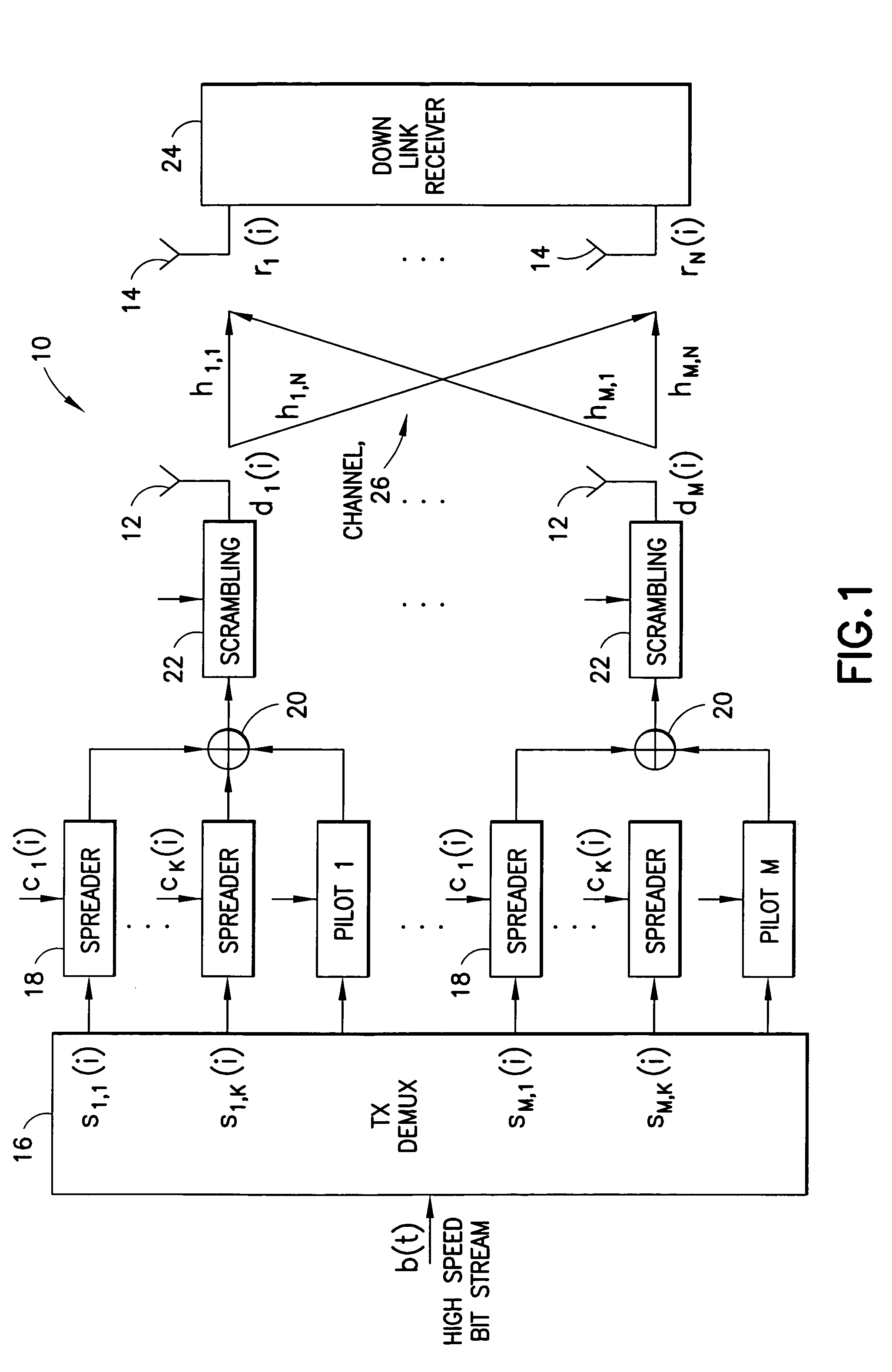
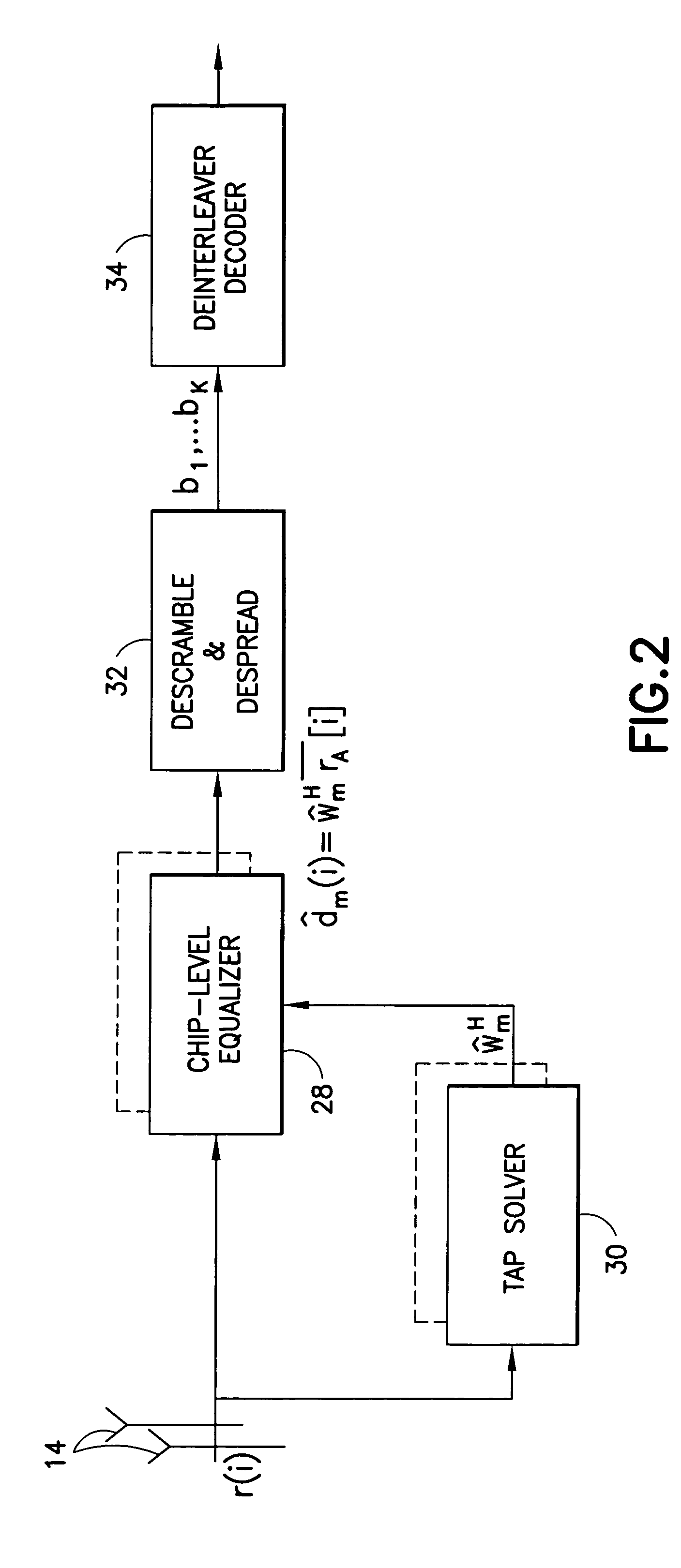
[0038]As used herein, the term CDMA refers generically to a spread spectrum communication system unless specifically stated otherwise (e.g., CDMA2000). The operators [ ]T and [ ]* indicate transpose, and the operator [ ]H indicates a Hermitian operation as known in the art. As an overview, the present invention is a reduced complexity FFT-based linear equalizer and further includes a complete parallel VLSI architecture for a proposed MIMO receiver. To further reduce the complexity, Hermitian optimization is disclosed that util...


PUM


Abstract

Disclosed is a LMMSE receiver that restores orthogonality of spreading codes in the downlink channel for a spread spectrum signal received over N receive antennas. The FFT-based chip equalizer tap solver reduces the direct matrix inverse of the prior art to the inverse of some submatrices of size N×N with the dimension of the receive antennas, and most efficiently reduces matrix inverses to no larger than 2×2. Complexity is further reduced over a conventional Fast Fourier Transform approach by Hermitian optimization to the inverse of submatrices and tree pruning. For a receiver with N=4 or N=2 with double oversampling, the resulting 4×4 matrices are partitioned into 2×2 block sub-matrices, inverted, and rebuilt into a 4×4 matrix. Common computations are found and repeated computations are eliminated to improve efficiency. Generic design architecture is derived from the special design blocks to eliminate redundancies in complex operations. Optimally, the architecture is parallel and pipelined.

Description

FIELD OF THE INVENTION[0001]The present invention relates generally to receivers and related methods for a spread spectrum communication system using multiple transmit and / or multiple receive antennas, and is particularly directed to a receiver using an equalizer, such as a linear minimum mean square error (LMMSE) based equalizer.BACKGROUND[0002]MIMO (Multiple Input Multiple Output) technology using multiple antennas at both the transmitter and receiver sides has recently emerged as one of the most significant technical breakthroughs in modern communications. The original MIMO is known as D-BLAST (see G. J. Foschini, “Layered space-time architecture for wireless communication in a fading environment when using multielement antennas”, Bell Labs Tech. J., pp. 41-59, 1996.) and a more realistic strategy as V-BLAST (see G. D. Golden, J. G. Foschini, R. A. Valenzuela, and P. W. Wolniansky, “DETECTION ALGORITHM AND INITIAL LABORATORY RESULTS USING V-BLAST SPACE-TIME COMMUNICATION ARCHITEC...

Claims


Application Information

Patent Timeline
Patent Type & Authority Patents(United States)
IPC IPC(8): H04B1/707H03H7/30
CPCH04B1/71055H04L25/0204H04L25/021H04L25/03038H04L25/0242H04L25/0328H04L2025/03375H04L2025/03426H04L2025/03477H04L2025/03605
Inventor GUO, YUANBINZHANG, JIANZHONGMCCAIN, DENNISCAVALLARO, JOSEPH R.
Owner VIVO MOBILE COMM CO LTD
Learn More