
Multiphoton-excitation observation apparatus

a technology of observation apparatus and photon beam, which is applied in the direction of luminescent dosimeters, optical radiation measurement, instruments, etc., can solve the problems of reducing resolution and s/n ratio, and being unable to acquire clear images

Active Publication Date: 2009-02-10
EVIDENT CORP
View PDF7 Cites 4 Cited by
  • Summary
  • Abstract
  • Description
  • Claims
  • Application Information

AI Technical Summary

Benefits of technology

The present invention provides a multiphoton-excitation observation apparatus that can acquire clear images from the surface layer portion to the deep layer portion of a specimen. The apparatus includes a light-source unit, an observation apparatus main unit, and a control apparatus. The control apparatus controls the incidence-adjusting unit of the observation apparatus based on the depth of the observation plane in the specimen. By adjusting the beam diameter of the laser light and the intensity of the laser light, the apparatus can acquire clear fluorescence images at any depth. The apparatus can also adjust the intensity of the laser light based on the depth of the observation plane, allowing for optimal imaging at different depths. The control apparatus can also store information about the intensity of the laser light and the number of irradiated pulses of laser light to simplify the processing involved. Overall, the apparatus provides a convenient and effective tool for multiphoton-excitation observation.

Problems solved by technology

However, even with multiphoton excitation, when observing a deep region exceeding a depth of 100 μm, for example, the effects of scattering, refraction, and absorption of the excitation light and the fluorescence by the specimen are strong, resulting in the problem that the resolution and S / N ratio decrease, which makes it impossible to acquire clear images.

Method used


Image

  • Multiphoton-excitation observation apparatus
  • Multiphoton-excitation observation apparatus
  • Multiphoton-excitation observation apparatus

Examples


first embodiment

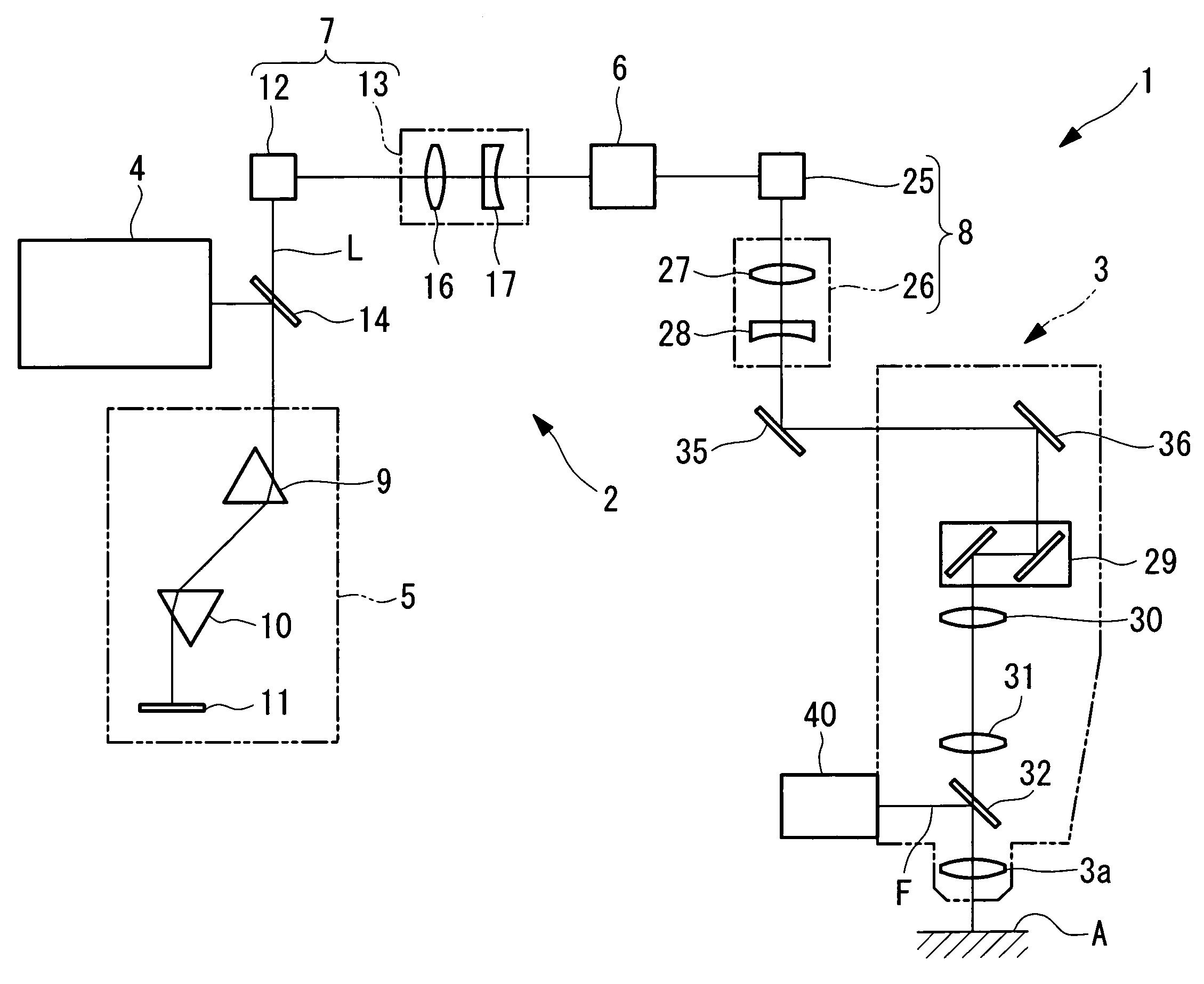
[0045]A multiphoton-excitation observation apparatus 1 according to the present invention will be described below with reference to FIGS. 1 to 4.

[0046]As shown in FIG. 1, the multiphoton-excitation observation apparatus 1 according to this embodiment is, for example, a multiphoton-excitation microscope including a light-source unit 2 and a fluorescence microscope main unit (observation apparatus main unit) 3 disposed after the light-source unit 2.

[0047]The light-source unit 2 includes a pulsed laser light source 4 for emitting ultra-short pulsed laser light L; a dispersion-compensating optical system 5 for compensating for group velocity dispersion of the ultra-short pulsed laser light L emitted from the pulsed laser light source 4; an acousto-optic device 6 for performing on / off or intensity modulation of the dispersion-compensated ultra-short pulsed laser light L; an incidence-adjusting unit 7, disposed between the acousto-optic device 6 and the pulsed laser light source 4, for al...

second embodiment

[0084]Next, a multiphoton-excitation observation apparatus 100 according to the present invention will be described below with reference to FIG. 5.

[0085]The multiphoton-excitation observation apparatus 100 according to this embodiment changes the beam diameter of the laser light according to the depth of the observation plane in the specimen.

[0086]In the description of this embodiment, parts having the same configuration as those in the above-described multiphoton-excitation observation apparatus 1 according to the first embodiment are assigned the same reference numerals, and a description thereof is omitted here.

[0087]FIG. 5 shows, in outline, the principal components of the multiphoton-excitation observation apparatus 100 according to this embodiment.

[0088]As shown in FIG. 5, the multiphoton-excitation observation apparatus 100 according to this embodiment includes, between the pulsed laser light source 4 and the fluorescence microscope main unit 3, an incidence-adjusting unit fo...

third embodiment

[0105]Next, a multiphoton-excitation observation apparatus according to the present invention will be described below with reference to FIG. 6.

[0106]The multiphoton-excitation observation apparatus according to this embodiment performs effective light detection to acquire clear observation images by adjusting the control of each component provided in the light-detecting device 40 according to the depth of the observation plane in the specimen A.

[0107]Parts having the same configuration as those in the multiphoton-excitation observation apparatus 1 according to the first embodiment described above are assigned the same reference numerals, and a description thereof is omitted in the description of this embodiment.

[0108]As shown in FIG. 6, the light-detecting device 40 according to this embodiment includes a focusing lens 41 for focusing fluorescence split off by the dichroic mirror 34 shown in FIG. 1, a pin-hole 42, a lens 43, a photomultiplier tube (PMT; light amplifying unit) 44, an...


PUM


Abstract

The invention provides a multiphoton-excitation observation apparatus comprising a light-source unit for emitting pulsed laser light; an observation apparatus main unit for irradiating a specimen with laser light emitted from the light-source unit and observing fluorescence emitted from the specimen; an incidence adjusting device, disposed between the light-source unit and the observation apparatus main unit, for adjusting the beam diameter of the laser light emitted from the light-source unit; and a control apparatus for controlling the incidence-adjusting unit according to the depth of an observation plane in the specimen.

Description

BACKGROUND OF THE INVENTION[0001]1. Field of the Invention[0002]This invention relates to multiphoton-excitation observation apparatuses.[0003]This application is based on Japanese Patent Application No. 2006-088760, the content of which is incorporated herein by reference.[0004]2. Description of Related Art[0005]A multiphoton-excitation apparatus is a known apparatus in the related art for observing the function of cells and so forth by irradiating a biological specimen or the like with ultrashort pulsed laser light from the surface thereof and detecting the fluorescence emitted from the surface or the interior of the specimen due to multiphoton absorption (for example, see Publication of Japanese Patent No. 2848952).[0006]Also known in the related art are scanning laser microscopes which acquire image data in a two-dimensional XY plane by detecting reflected light or transmitted light from a specimen while scanning a spot of light in the two-dimensional XY plane on the specimen, a...

Claims


Application Information

Patent Timeline
Patent Type & Authority Patents(United States)
IPC IPC(8): G02B21/06
CPCG01N21/6458
Inventor OKADA, JUNICHIUENO, MAKIOMATSUKAWA, YASUNARI
Owner EVIDENT CORP
Learn More