
Cutting method using a laser having at least one ytterbium-based fiber, in which at least the power of the laser source, the diameter of the focused beam and the beam quality factor are controlled

a laser source and laser cutting technology, applied in laser beam welding apparatus, active medium shape and construction, manufacturing tools, etc., can solve the problems of poor cutting quality and cutting speed, and the solution is not satisfactory

Inactive Publication Date: 2012-10-02
LAIR LIQUIDE SA POUR LETUDE & LEXPLOITATION DES PROCEDES GEORGES CLAUDE
View PDF14 Cites 31 Cited by
  • Summary
  • Abstract
  • Description
  • Claims
  • Application Information

AI Technical Summary

Benefits of technology

The invention is a laser cutting method that uses a laser beam generated by a ytterbium-containing fiber to melt the workpiece and perform the actual cutting. This method has technical effects that include improved cutting precision and efficiency, as well as reduced damage to the workpiece.

Problems solved by technology

However, this solution is not satisfactory from the industrial standpoint as it gives poor results in terms of cutting quality and cutting speed, not only because of beam quality factors (BPP) unsuitable for laser cutting but also because the transverse energy distribution in the beam is not Gaussian but has a top-hat profile, while beyond the focal point the transverse energy distribution is even random.
The problem that arises is therefore how to provide an improved laser cutting method, which does not have the abovementioned drawbacks and limitations and can achieve, depending on the thickness in question, speeds ranging up to 15 to 20 m / min, or even higher, and good cutting quality, that is to say straight cutting faces, with no burrs and limited roughness.

Method used


Image

  • Cutting method using a laser having at least one ytterbium-based fiber, in which at least the power of the laser source, the diameter of the focused beam and the beam quality factor are controlled
  • Cutting method using a laser having at least one ytterbium-based fiber, in which at least the power of the laser source, the diameter of the focused beam and the beam quality factor are controlled
  • Cutting method using a laser having at least one ytterbium-based fiber, in which at least the power of the laser source, the diameter of the focused beam and the beam quality factor are controlled

Examples


Embodiment Construction

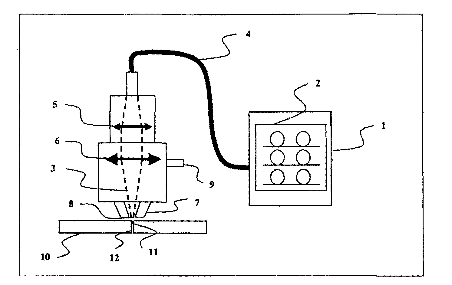
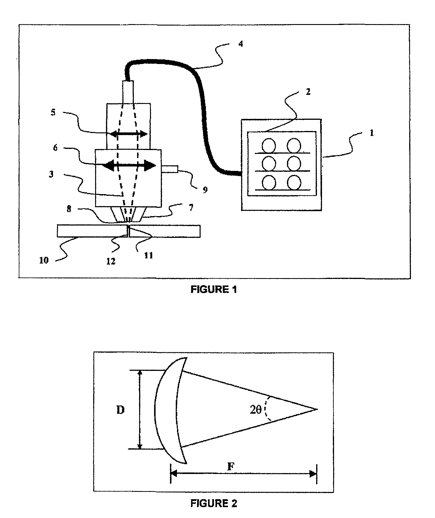
[0019]According to the invention, the laser beam is selected so as to have:[0020]a power of less than 100 kW;[0021]a power density of at least 1 MW / cm2;[0022]a focused beam diameter of at least 0.1 mm; and[0023]a quality factor (BPP) of less than 10 mm·mrad.

[0024]In addition, according to the invention, the laser beam generation means comprise at least one exciter element, preferably several exciter elements, which cooperate with at least one excited element, also called amplifying medium, in order to generate the laser beam. The exciter elements are preferably several laser diodes, whereas the excited element(s) is (are) preferably a silica fiber with an ytterbium core or preferentially a plurality of such fibers.

[0025]Furthermore, within the context of the invention, the terms “laser beam generation means” and “resonator” will be used indiscriminately. This type of laser source is usually called a “fiber” laser or “ytterbium fiber” laser source since the amplifying medium is an ar...


PUM

PropertyMeasurementUnit
wavelengthaaaaaaaaaa
poweraaaaaaaaaa

Abstract

The invention relates to method for cutting a part using a laser beam, involving the use of laser beam generation means comprising at least one ytterbium-based fibre having a wavelength of between 1 and 4 μm in order to generate the laser beam. The laser beam is selected to have a power of less than 100 kW, a power density of at least 1 MW / cm2, a focused beam diameter of at least 0.1 mm and a quality factor (BPP) of less than 10 mm·mrad.

Description

[0001]This application is a §371 of International PCT Application PCT / FR2007 / 050673, filed Jan. 22, 2007.BACKGROUND[0002]1. Field of the invention[0003]The invention relates to a laser cutting method using an ytterbium-based fiber laser source.[0004]1. Related Art[0005]Laser cutting using a CO2 laser source for generating a laser beam with a wavelength of 10.6 μm, with a power ranging up to 6 kW at the present time, is widely used in the industry as this type of source gives good beam characteristics, namely a good quality factor (M2, BPP, etc.) and a good spatial energy distribution (TEM01*).[0006]It is possible with these CO2 laser sources to cut metals and their alloys, such as aluminum and its alloys, stainless steel, carbon steel, mild steel, etc., or any other nonmetallic material, such as wood, board, ceramics.[0007]However, the cutting speeds that can be achieved and the cutting quality that results therefrom are highly variable, depending on the material to be cut and, more...

Claims


Application Information

Patent Timeline
Patent Type & Authority Patents(United States)
IPC IPC(8): B23K26/38B23K26/14B23K26/08H01S3/06
CPCB23K26/0639B23K26/0648B23K26/0665B23K26/38B23K26/125B23K26/14B23K26/123B23K26/064
Inventor CHOUF, KARIMMAAZAOUI, HAKIMVERNA, ERICBRIAND, FRANÇIS
Owner LAIR LIQUIDE SA POUR LETUDE & LEXPLOITATION DES PROCEDES GEORGES CLAUDE
Learn More