Cooling element

a cooling element and cooling element technology, applied in the field of industrial reactors, can solve the problems of extreme working conditions in the reactor, weak corrosion, and weak corrosion resistance, and achieve the effects of avoiding drawbacks of prior art, avoiding seams in the structure, and good heat transfer

Active Publication Date: 2008-12-16
OUTOTEC OYJ
View PDF11 Cites 2 Cited by
  • Summary
  • Abstract
  • Description
  • Claims
  • Application Information

AI Technical Summary

Benefits of technology

[0006]The solution according to the invention has many advantages, and by means of the invention, drawbacks of the prior art can be avoided. The structure of the cooling element according to the invention enables a good heat transfer between the housing comprising the cooling element and the lining made of fireproof material. The housing is preferably made of one single piece, so that seams in the structure are avoided. The housing and the lining elements are combined so that the fireproof lining elements may advantageously move with respect to the housing in the vertical direction. Now the tendency of the accretions located on the furnace bottom to move the whole cooling element is eliminated. On the surface of the housing, there are made vertical grooves, in which the lining elements made of fireproof material can be fitted owing to their bracket-like edge parts. A groove is preferably designed so that it narrows from the groove bottom towards the surface. This shape of the grooves helps the lining elements to be attached in the housing, and ensures that a good heat transfer is maintained between said surfaces. Advantageously the cooling element is installed in the furnace so that the grooves are positioned in the vertical direction. The bottom part of the housing provided in the cooling element is narrowed downwardly, in which case its shape preferably conforms to the shape of the supporting brick provided on the furnace bottom. Thus the effect of the motions caused by the thermal expansion of the supporting brick in the cooling element is attenuated.
[0007]The cooling element can be built as a ready-made structure already before it is installed in the furnace. As an alternative, the housing part and the lining elements can be built on site at the same time as the cooling element is installed in the furnace. The cooling element is easy and economical to manufacture, it is rapidly installed and thus it helps to cut down the time required by the furnace repairs. In the depth direction of the cooling element, the lining elements extend to outside the housing part, in which case they protect the cooling element structure better and thus reduce thermal losses in the furnace. Preferably the lining elements cover the whole surface of the housing, so that the copper surface of the cooling element does not get into contact with the melt. The cooling elements according to the invention are interconnected at the junctions provided in the elements, so that in an auxiliary groove formed in the junction, there are placed lining elements in the vertical direction. Thus the seam is advantageously covered. In the cooling element according to the invention, there are avoided horizontal seams that could cause serious melt leakages. By employing the cooling element structure according to the invention, it is possible to avoid the use of a solder material between the housing and the lining.

Problems solved by technology

The working conditions prevailing in the reactor are extreme, and the cooling elements may be subjected for example to powerful corrosion and erosion strain caused by the furnace atmosphere and molten contacts.
However, the lining tends to thin out in the course of time, and this may result in a situation where the molten metal gets into contact with the surface of the cooling element made of copper.
The difficulty in the production of known cooling elements is to achieve a good contact between the fireproof lining and the cooling element.
The protective effect of the fireproof lining is greatly dependent on a successful installation, and in most cases the cooling properties of the element cannot be fully utilized.
Moreover, a drawback of known cooling elements is the fact that the grooves made for fastening the fireproof material are positioned horizontally in the furnace.
Thus the motion caused by the thermal expansion of the supporting brickwork used in the furnace bottom, as well as the motion of the accretions accumulated of the solidifying molten phases on the furnace bottom cause tensions in linings located in the horizontal grooves, which may result in the shifting of the cooling element and the creation of harmful cracks.
In addition, cooling elements made of several pieces contain a lot of horizontal seams where harmful leakages may occur.

Method used


Image

  • Cooling element
  • Cooling element
  • Cooling element

Examples


Embodiment Construction

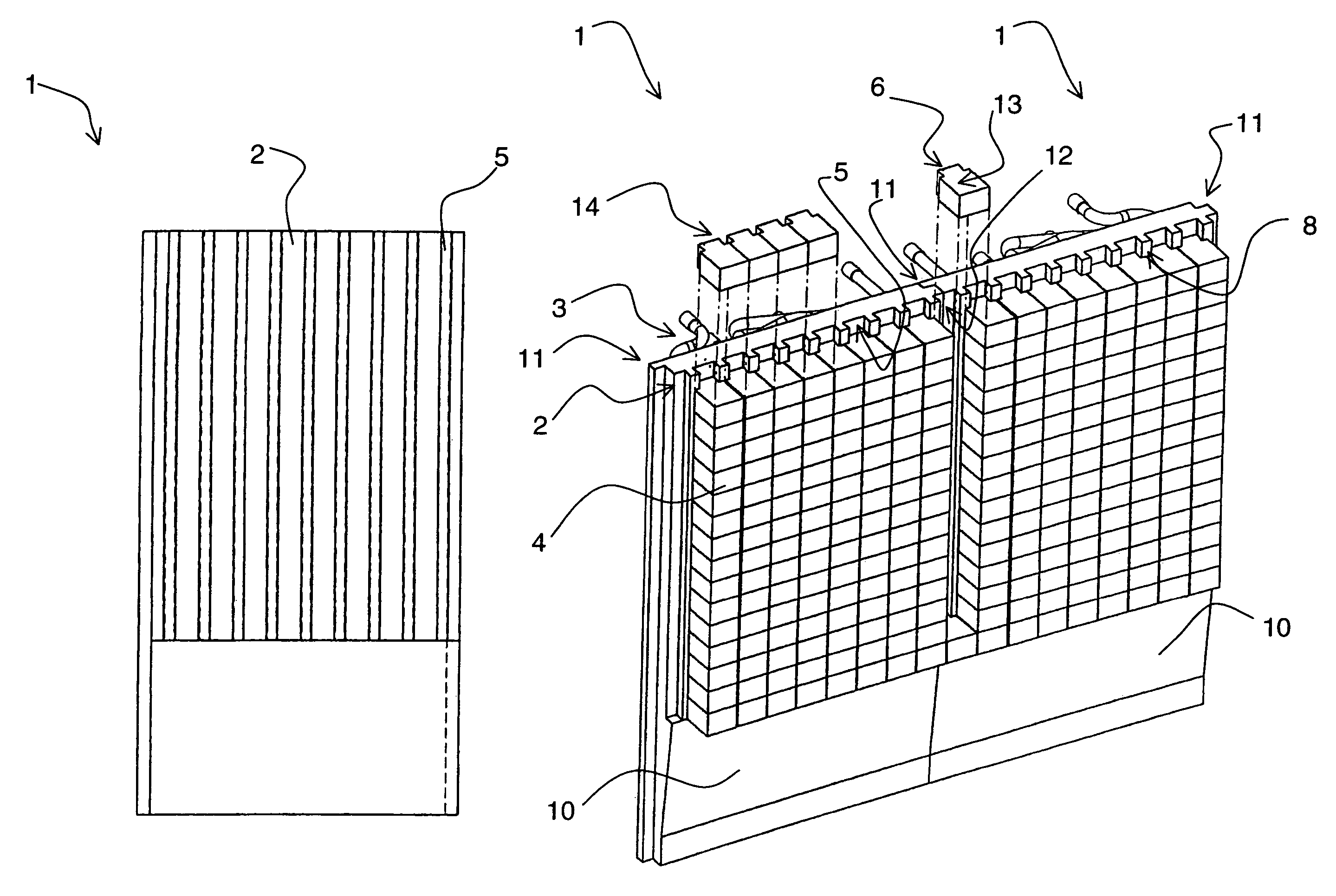
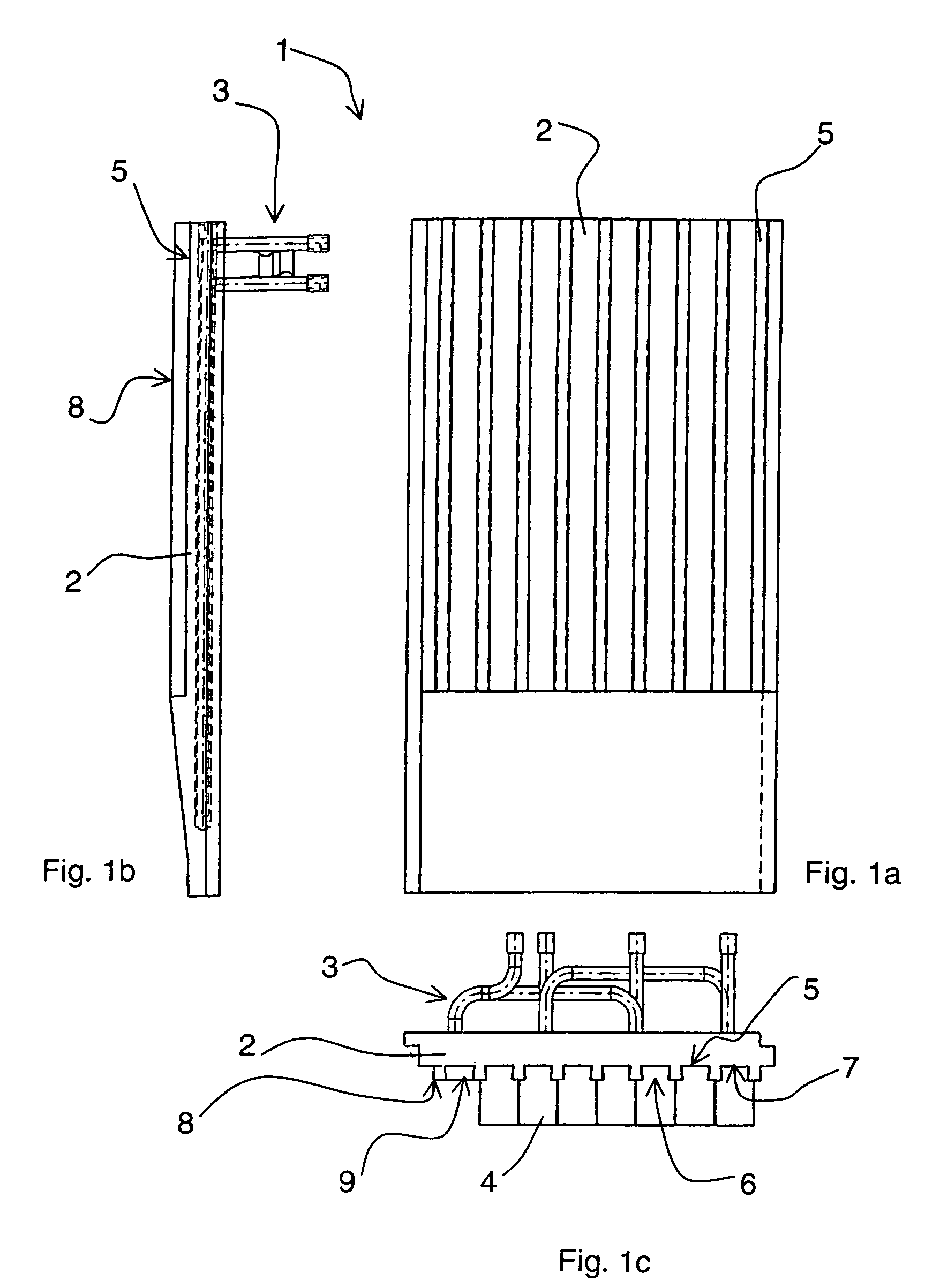
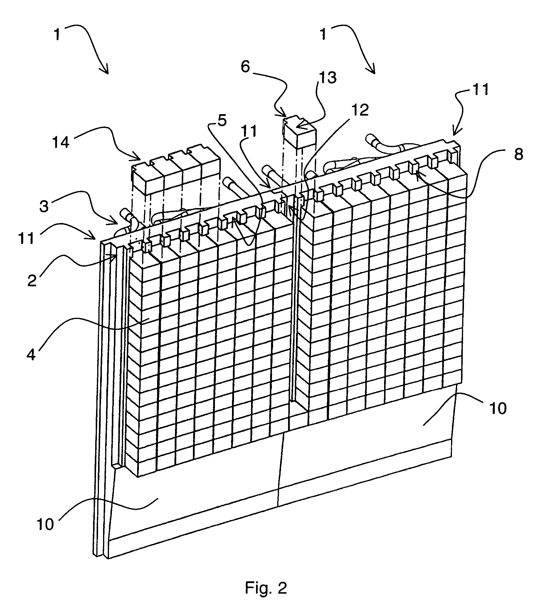
[0011]FIGS. 1a, 1b and 1c illustrate a cooling element 1 according to the invention, which is suited to be used for instance in the wall structure of a flash smelting furnace. FIG. 1a is a front-view illustration of the element, FIG. 1b is a side-view illustration and FIG. 1c a top-view illustration. The cooling element 1 comprises a copper housing 2 made of one single piece, in which a channel system 3 is formed for the circulation of the cooling medium. In addition, the cooling element comprises a sufficient number of lining elements 4 made of a fireproof material, such as chromium magnesite brick, which lining elements are connected to the housing 2. The housing and the lining elements are provided with elements for fastening them together. On the surface 8 of the housing, there are formed vertical grooves 5, in which the lining elements 4 are positioned in the vertical direction on top of each other, so that the whole groove is filled in the vertical direction of the cooling ele...


PUM

PropertyMeasurementUnit
Widthaaaaaaaaaa
Widthaaaaaaaaaa
Depthaaaaaaaaaa

Abstract

Disclosed is a method for manufacturing a cooling element (1) to be used in the structure of a furnace used in metal processes, such as a flash smelting furnace, a blast furnace, an electric furnace or other metallurgical reactor, the cooling element having a copper housing (2) made of one single piece, in which housing there is formed a channel system (3) for the circulation of the cooling medium, lining elements (4) made of fireproof material, the housing and lining element including means for connecting them together, and the lining element (4) and the housing (2) are connected so that the lining element (4) can move in the vertical direction with respect to the housing (2). Also disclosed is a cooling element.

Description

[0001]The invention relates to a method for manufacturing a cooling element and to a cooling element.BACKGROUND OF THE INVENTION[0002]In connection with industrial reactors, particularly reactors used in metal processes, such as flash smelting furnaces, furnaces and electric furnaces, there are used massive cooling elements that are usually made of copper. Typically cooling elements are water-cooled and thus provided with cooling water channel systems. In pyrometallurgical processes, the reactor brickworks are protected so that the heat directed to the brickwork surfaces is through the cooling element transferred to water, in which case the wearing of the lining is essentially reduced in comparison with a reactor that is not cooled. The reduction in wearing is achieved by a so-called autogenous lining solidified on the surface of the fireproof lining, which autogenous lining is formed of slag and other substances separated from the molten phases.[0003]On the surface of the cooling e...

Claims


Application Information

Patent Timeline
IPC IPC(8): C21B7/10C21C5/46C21C5/52F27B3/24F27D1/12F27D9/00
CPCC21B7/10F27D1/12F27B3/24F27D2009/0062F27D2009/0048F27D2009/0054F27D2009/0032F27D9/00
Inventor SAARINEN, RISTOHUGG, EEROSEPPALA, KAI
Owner OUTOTEC OYJ
Why Eureka
Try Eureka