Apparatus and method for facilitating accurate placement and installation of molding

a technology of accurate placement and installation, applied in the direction of building components, structural elements, building scaffolds, etc., can solve the problems of difficult installation of corner pieces, difficult cooperation of two or more workers, and notoriously difficult installation of molding at the corner intersection of two adjacent walls, so as to increase the accuracy of molding installation

Inactive Publication Date: 2008-11-18
BARONE JOSEPH
View PDF20 Cites 13 Cited by
  • Summary
  • Abstract
  • Description
  • Claims
  • Application Information

AI Technical Summary

Benefits of technology

[0005]To help solve these problems, the present invention mates the two corner pieces of molding with an aligning member such that both corner pieces are held together during installation. With the corner pieces held together by the aligning member, a person can use one hand to hold both corner pieces in place while using the other hand to secure the molding to the wall or ceiling. This helps increase the accuracy of the molding installation since both pieces are held at the corner at the same time. Use of the aligning member also allows an installer to readily see if shims or spacers are needed to make the alignment perfect between the corner pieces.
[0008]The aligning member may be made in many different configurations or forms. All that is important is that the aligning member joins the two corner molding pieces together allowing for easier and more accurate installation. In one embodiment, the aligning member is a singular piece of material with two arms each having a proximal and distal end, where the proximal ends come together at an angle. The aligning member is not limited to “two-arm” embodiments however; any number of arms may be present. Each arm also has a length between its proximal and distal ends such that it can engage a precut groove or hole within an end of the molding. In another embodiment, the aligning member resembles a two-headed dowel, having two circular arms that engage the molding within circular grooves or holes. In another embodiment, the aligning member is a singular piece of material with a rounded inside surface and two straight segments extending from the rounded inside surface, wherein each straight segment is inserted into an opening cut into an end of a piece of molding. In other embodiments, the aligning member may be rectangular, resembling a rectangular piece of material bent somewhere in a middle portion of the rectangle such that there are at least two rectangular arms for placement within the molding ends. In another embodiments, the aligning member may have a circular surface resembling a biscuit and bent in a way as to provide at least two arms for placement within the molding ends. In yet other embodiments, the arms may be tapered.
[0009]Use of the aligning member also allows the installer to adjust the alignment of the corner pieces to fit within unique contours of a desired wall corner. Since construction is an imprecise art, wall intersections are often imperfect. A certain amount of “fine-tuning” is therefore necessary to achieve accurate alignment between two pieces of molding. With the aligning member in place, the corner pieces may be slightly adjusted relative one another, facilitating perfect alignment at the actual wall corner. In an embodiment of the aligning member with two straight elongated arms, the molding may be slightly adjusted by sliding the molding along the length of the arm. This is a form of lateral adjustment of the corner joint. In another embodiment of the aligning member having two rectangular arms, the molding may be slightly adjusted by sliding the molding along the length of the rectangular arm. It is also possible to have curved arms on the aligning member.
[0010]Fine adjustment of the corner pieces in the vertical direction may be accomplished by cutting the receiving hole within an end of the molding larger than the cross-section dimension of an arm of the aligning member. For example, cutting a hole that is wide enough to receive the aligning member arm but is slightly larger in the vertical direction on either side of the arm will allow a certain amount of movement that can be used to vertically fine adjust the corner pieces.

Problems solved by technology

Molding placed adjacent to the floor is referred to as “base molding” and molding placed adjacent the ceiling is referred to as “crown molding.” The installation of this molding at the corner intersection of two adjacent walls is notoriously difficult, sometimes requiring the cooperation of two or more workers.
Installing these corner pieces is difficult because it is not always easy to orient molding pieces properly along the edge of the wall.
During installation, these pieces often become misaligned and contain visible flaws.
This imprecise method frequently results in inaccurate placement resulting in misalignment of intersecting crown molding segments at the corners of the room.
These imprecise joints at the corners are unattractive and detract from the appearance of the molding.
As a result, installation of molding is usually too difficult for the average homeowner or do-it-yourselfer.

Method used


Image

  • Apparatus and method for facilitating accurate placement and installation of molding
  • Apparatus and method for facilitating accurate placement and installation of molding
  • Apparatus and method for facilitating accurate placement and installation of molding

Examples


Embodiment Construction

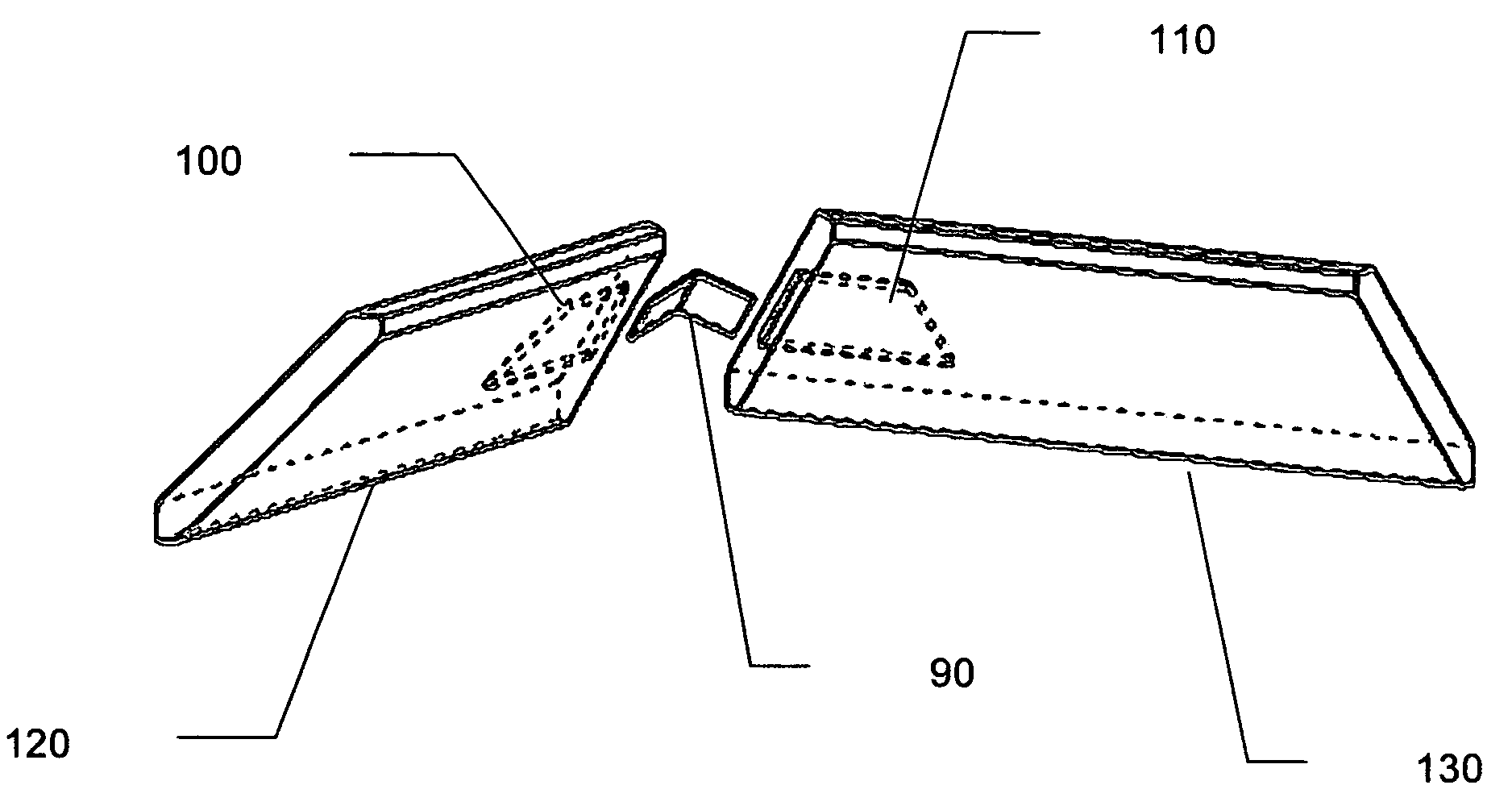
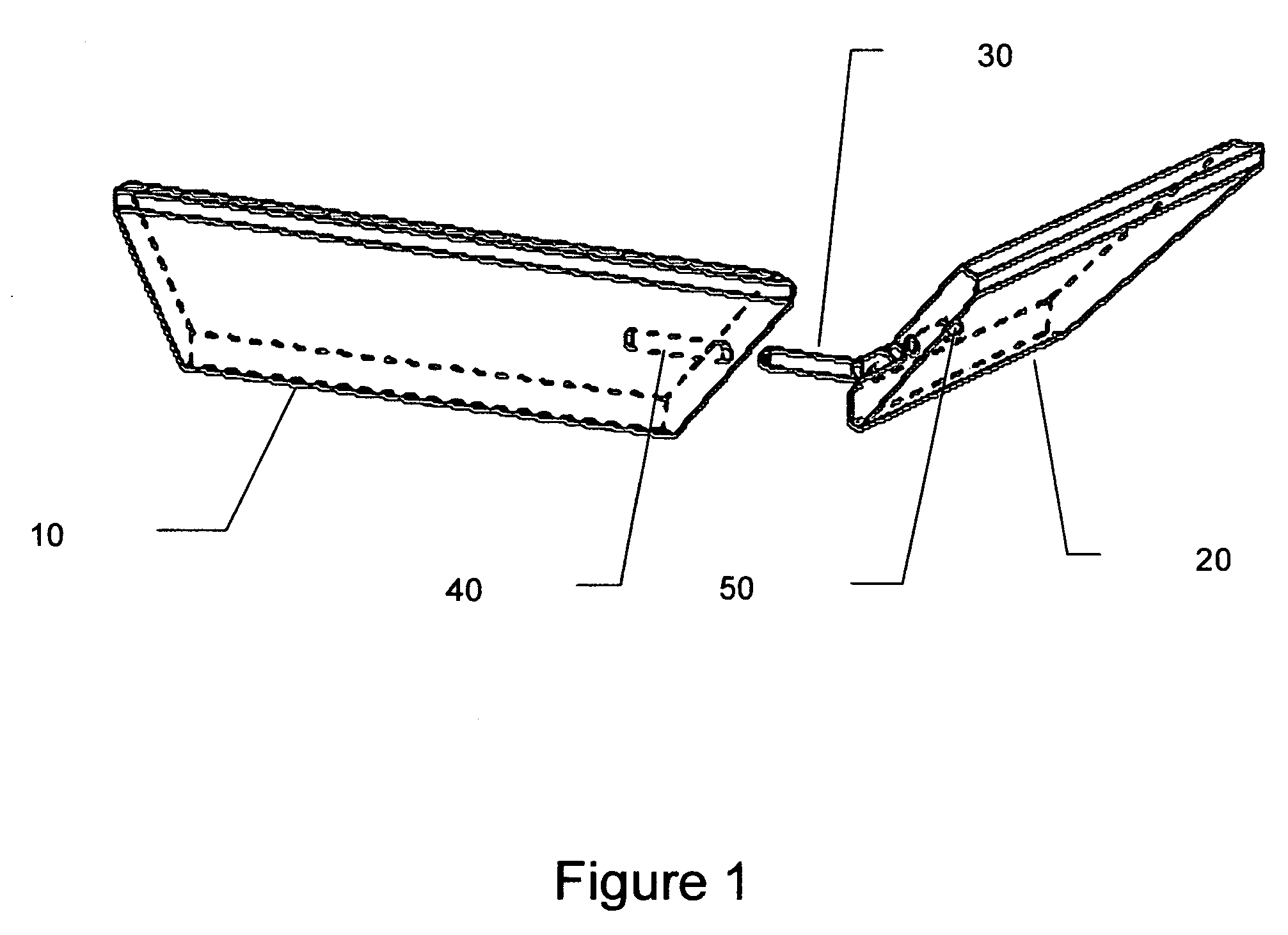
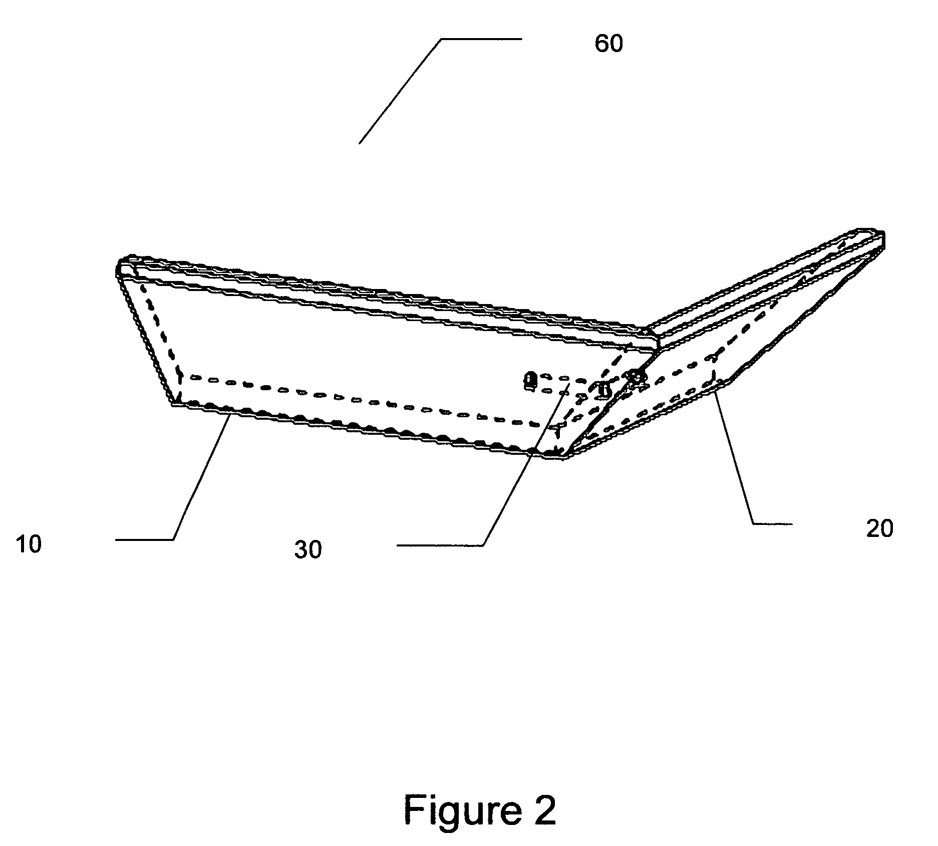
[0023]Referring to FIG. 1, an exploded view of two pieces of molding 10, 20 that will form an outside corner is shown with an embodiment of an aligning member 30 in between. Each piece of molding 10, 20 has a receiving hole 40, 50 drilled into its end to allow insertion of an arm of the aligning member 30. As shown in FIG. 2, once assembled, the two pieces of molding will be held together by aligning member 30 allowing an installer to hold the assembled corner 60 with one hand and secure the assembled corner 60 to the wall, ceiling or floor with the other hand.

[0024]As depicted in FIGS. 1 and 2, an embodiment of the aligning member 30 resembles a “two-headed dowel” having arms with a circular cross-section and an angle formed between the two arms. The length of the arms must be sufficiently long and the arms must be sufficiently strong to hold the weight to a piece of the molding since only one piece of the molding may be otherwise supported during installation. FIGS. 3 and 4 show t...


PUM


Abstract

An apparatus and method for installation of molding is disclosed. With the apparatus and method, corner pieces are held in alignment during installation. This allows a person to hold both corner pieces in place with one hand while using the other hand to secure the molding to the wall or ceiling, thereby facilitating an accurate alignment. Moreover, use of an aligning member allows the installer to “fine-tune” the alignment of the corner pieces to fit unique contours of a desired wall corner. Before securing the molding to the wall, the corner pieces may be moved laterally or vertically along the aligning member to help find a perfect alignment. Several embodiments of the aligning member are disclosed, including members with varying angles for different corner segments, flexible members, and members with varying cross-sections.

Description

BACKGROUND OF THE INVENTION[0001]This invention relates to an apparatus and method for accurate placement and installation of molding.[0002]Molding is used as finish trim on walls either adjacent the floor and ceiling. This molding serves many different functions, including the decorative enhancement of a room and concealment of an intersection between a ceiling and walls. Molding placed adjacent to the floor is referred to as “base molding” and molding placed adjacent the ceiling is referred to as “crown molding.” The installation of this molding at the corner intersection of two adjacent walls is notoriously difficult, sometimes requiring the cooperation of two or more workers. For example, at a 90-degree inside or outside corner segment of a room, it is a well-known and established practice to miter-cut an end of two separate pieces of molding strips at opposing 45-degree angles. With an end of each molding strip cut at 45-degrees, they form the required 90-degree angle when posi...

Claims


Application Information

Patent Timeline
IPC IPC(8): E04D1/36E04F19/04E04F21/00
CPCE04F21/0069E04F19/0436Y10T403/725E04F19/0495F16B2200/65
Inventor BARONE, JOSEPH
Owner BARONE JOSEPH
Why Eureka
Try Eureka