
Step time change compensation in an industrial automation network

a technology of industrial automation and compensation, applied in the field of time synchronization technology, can solve the problems of not achieving a high level of synchronization accuracy or convergence speed, unable to account for step changes in the master clock, and difficult for the system to perform certain control functions

Active Publication Date: 2008-11-04
ROCKWELL AUTOMATION TECH
View PDF20 Cites 140 Cited by
  • Summary
  • Abstract
  • Description
  • Claims
  • Application Information

AI Technical Summary

Benefits of technology

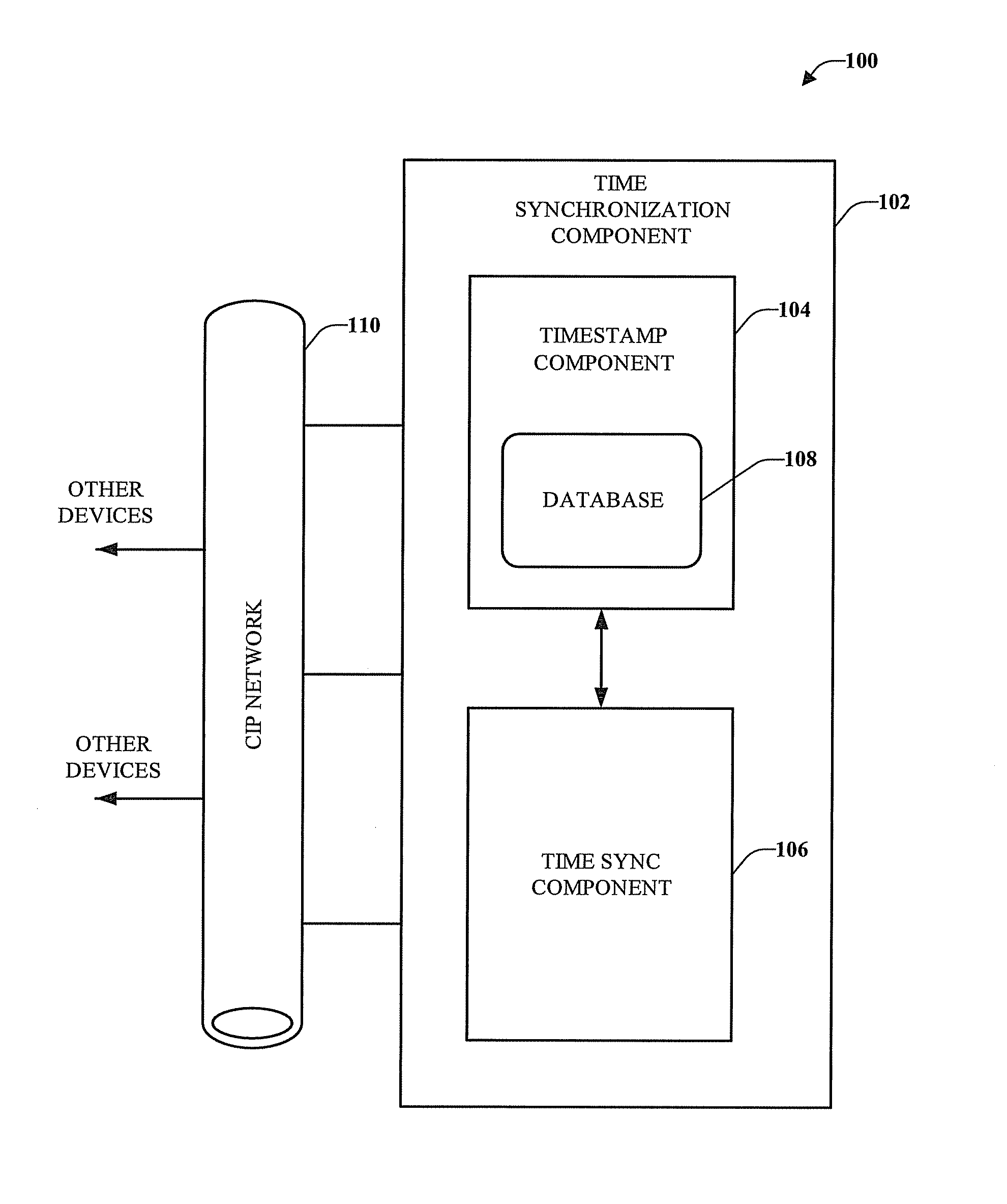
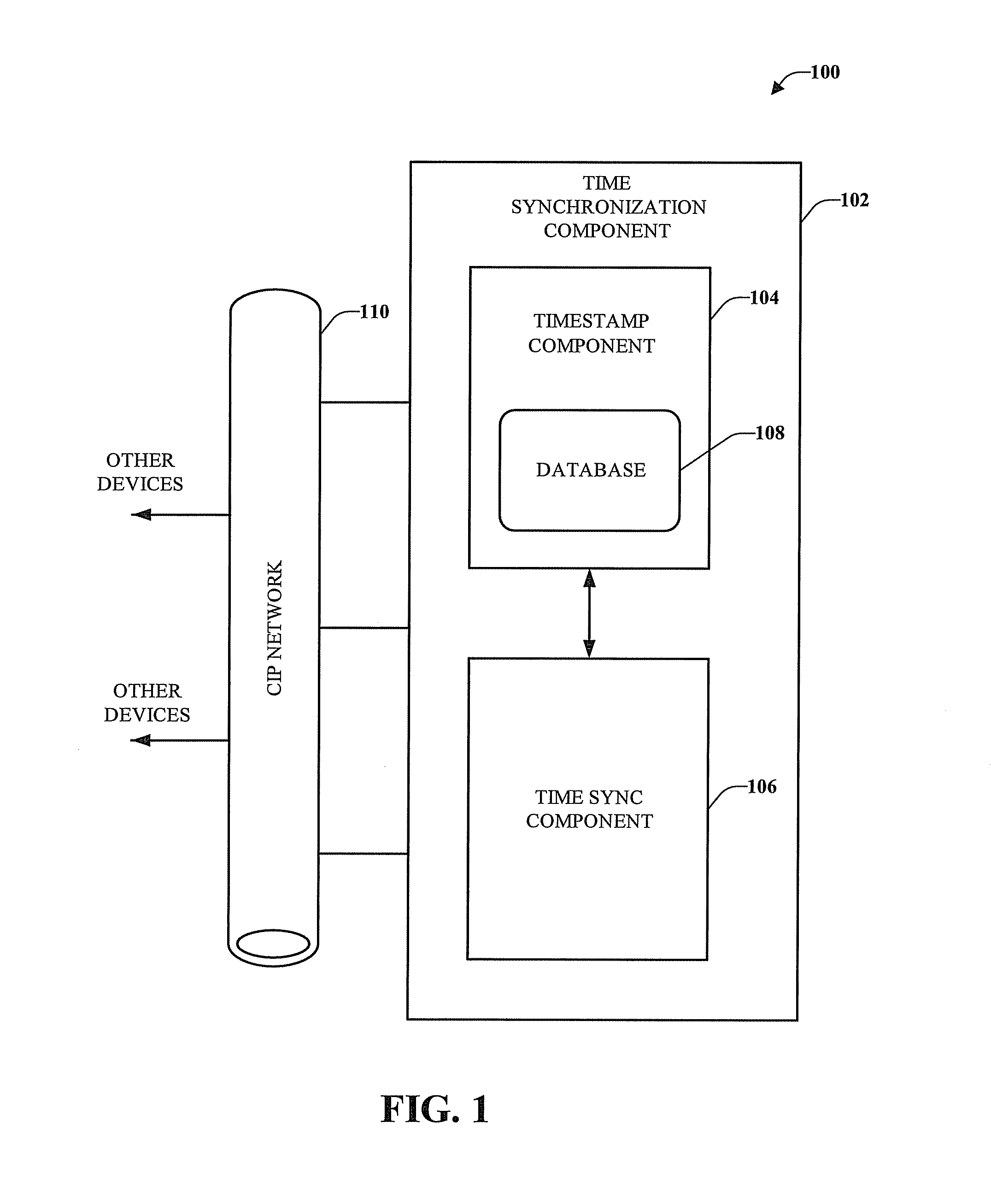
[0012]In accordance with one or more embodiments and corresponding disclosure thereof, various aspects are described in connection with a Common Industrial Protocol (CIP) network (e.g., DeviceNet, ControlNet, EtherNet / IP, etc.). According to an embodiment is a system that enables motion control and includes a time synchronization component that provides connectivity with at least one of a CIP network and also includes a timestamp component that interacts with a time sync component. The time synchronization component can provide compensation for step changes that may occur when utilizing motion control systems and methods in order to handle discrepancies caused by various conditions, disruptions, or other factors efficiently.
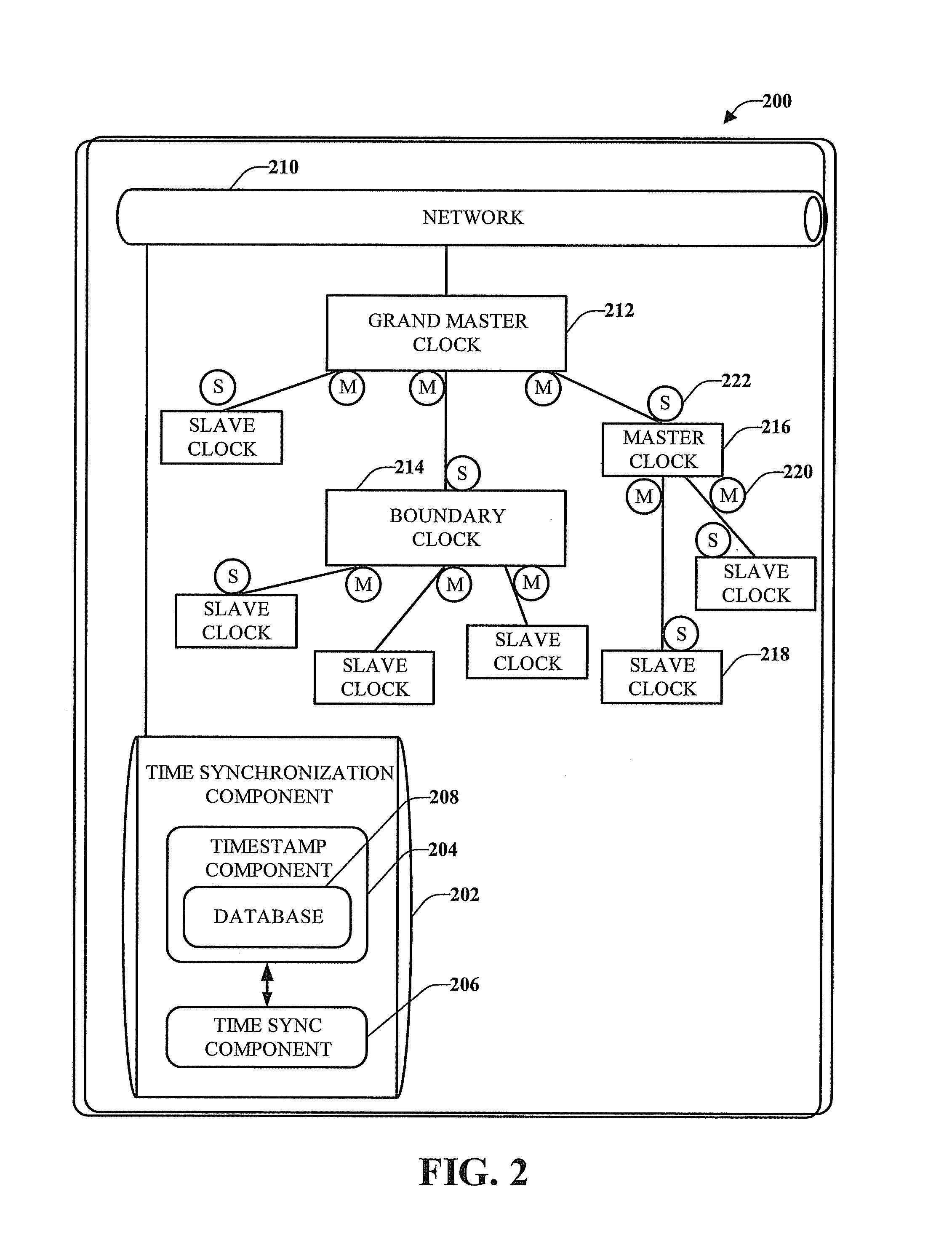
[0013]In accordance with another embodiment of the innovation described herein, the time synchronization component can work in conjunction with a CIP and can employ a timestamp component and a time sync component to determine if a step change has occurred in the system. The time synchronization component can verify that a step change has occurred in the system and can correct for those step changes across the time devices in the system. The time synchronization component can direct a timestamp component to store timestamps and offsets for the various clock nodes in a database. The clocks within the system can be synchronized to a specified uncertainty, so that measurements of any time interval between the clocks are not greater than the specified uncertainties.
[0014]In accordance with another embodiment of the innovation described herein, a time synchronization offset clock model can be a network of devices that share the same concept of a system time and each of the devices can also have a local clock value based on frequency disciplined timing and related to system time by a system offset value. For example, the model can allow each device to maintain a local time independence from all of the other devices, but share a common notion of system time associated with a grandmaster clock and as such, system time can change without requiring changes to the local clocks (e.g., microprocessors, embedded controllers, programmable logic controllers (PLC)). The time synchronization offset clock model can define a mechanism to maintain a consistent set of timestamps in the presence of step changes to the grandmaster clock and associated system time. A step change in the system time can effectively cause a shift in the time base of the system and step changes to the grandmaster clock time can be propagated through the system. The step change in the grandmaster clock can occur for various reasons including, power outages, manual reset of the clock, the system loses a satellite signal, and the like.

Problems solved by technology

Existing time synchronization protocols such as NTP and SNTP do not achieve a high level of synchronization accuracy or convergence speed.
In particular, those protocols do not account for step changes in the master clock, (e.g., the clock is changed manually, the clock loses the time reference satellite for a given time period, etc.).
Any step change seen by the master clock will also be seen by the associated slave clocks and this makes it difficult for the system to perform certain control functions.
In yet another example, when a failure occurs in high speed or unsupervised machinery it is difficult or nearly impossible to tell how the failure occurred without an understanding of the absolute time of the machinery.
In other words, even if events were timestamped using one of the aforementioned protocols, the timestamps may not be correct due to step changes in the system time.
Step changes in a master clock may result in having to discard otherwise high-quality product if those step changes that occurred can not be determined accurately.
In addition, systems or networks are often made up of equipment from various manufacturers and in many instances each manufacturer can have its own specific time logging system, further compounding time synchronization problems.
In a steel rolling application the consequence may be much worse, resulting in motor failures, premature wear, roller damage, total equipment failure, costly machine rebuilding, etc.

Method used


Image

  • Step time change compensation in an industrial automation network
  • Step time change compensation in an industrial automation network
  • Step time change compensation in an industrial automation network

Examples


Embodiment Construction

[0030]Various embodiments are now described with reference to the drawings, wherein like reference numerals are used to refer to like elements throughout. In the following description, for purposes of explanation, numerous specific details are set forth in order to provide a thorough understanding of one or more aspects. It may be evident, however, that various embodiments may be practiced without these specific details. In other instances, well-known structures and devices are shown in block diagram form in order to facilitate describing these embodiments.

[0031]As utilized in this application, the terms “component,”“system,” and the like are intended to refer to a computer-related entity, either hardware, a combination of hardware and software, software, software in execution, and / or firmware. For example, a component can be, but is not limited to being, a process running on a processor, a processor, an object, an executable, a thread of execution, a program, and / or a computer. By ...


PUM


Abstract

One or more embodiments provide Common Industrial Protocol (CIP) based time synchronization systems and methods. The CIP Sync solution can be part of Ethernet / IP and can be based on standard UDP (User Datagram Protocol) and / or IEEE 1588 (Time Synchronization) Ethernet technology. According to an embodiment is a system that compensates for step changes in a master clock.

Description

CROSS-REFERENCE TO RELATED APPLICATIONS[0001]This application claims the benefit of U.S. Provisional Patent Application Ser. No. 60 / 749,318 entitled “STEP TIME CHANGE COMPENSATION IN AN INDUSTRIAL AUTOMATION NETWORK” and filed Dec. 9, 2005.TECHNICAL FIELD[0002]The following description relates generally to time synchronization technology and more particularly to compensation for system step changes across a network of distributed devices in order to accurately represent time.BACKGROUND[0003]Synchronized time is critical in the motion control and other industries as companies continue to develop systems and methods for obtaining higher degrees of device interoperability. This is significant for companies that employ distributed motion control applications requiring tight time synchronization between system devices. This need for higher performance applications is coupled with the necessity for synchronizing clocks across a distributed network (e.g., Ethernet). Every aspect of managin...

Claims


Application Information

Patent Timeline
IPC IPC(8): H04J3/06
CPCH04J3/0697H04J3/0667
Inventor RISCHAR, CHARLES M.HARRIS, KENDAL R.CHAFFEE, MARK
Owner ROCKWELL AUTOMATION TECH
Learn More