Pulse generation circuit

a generation circuit and pulse technology, applied in the direction of pulse technique, generating/distributing signals, instruments, etc., can solve the problems of inconstant output, affecting the speed of the pulse, and increasing the size of the timing control unit, so as to achieve high (hi) voltage levels

Inactive Publication Date: 2008-11-04
FUJITSU LTD
View PDF19 Cites 2 Cited by
  • Summary
  • Abstract
  • Description
  • Claims
  • Application Information

AI Technical Summary

Benefits of technology

[0016]Such being the case, it is an object of the present invention to provide a pulse generation circuit that is light in input load and capable of self-resetting.
[0022]In the pulse generation circuit, the delay circuit, when receiving a stop signal, may stop the output of the output pulse in a way that keeps high (Hi) voltage levels of the gate electrodes of the P-type MOS transistor and of the first N-type MOS transistor.

Problems solved by technology

In the case of the pulse generation circuits in FIGS. 18, 19 and 21, a CLK load on a module is large, and a large number of transistors bring about an increase in size of a timing control unit, resulting in hindrance to a speedup.
Still further, in the case of employing the dynamic type pulse generation circuit in FIG. 20, there is a possibility that the output might get inconstant when turned on power-supply.
Then, if the pulse generation circuit is constructed by use of SOI CMOS (Silicon On Insulator (especially PD) Complementary Metal Oxide Semiconductor) and when an operation cycle fluctuates in the circuit, there is a possibility that an internal timing deviates due to a history effect, and inconvenience occurs.

Method used


Image

  • Pulse generation circuit
  • Pulse generation circuit
  • Pulse generation circuit

Examples


first embodiment

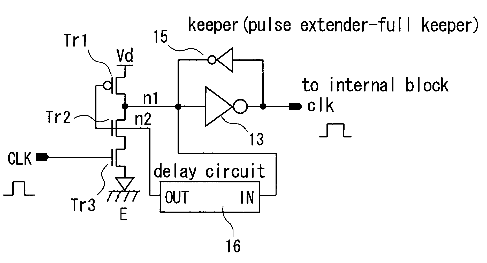
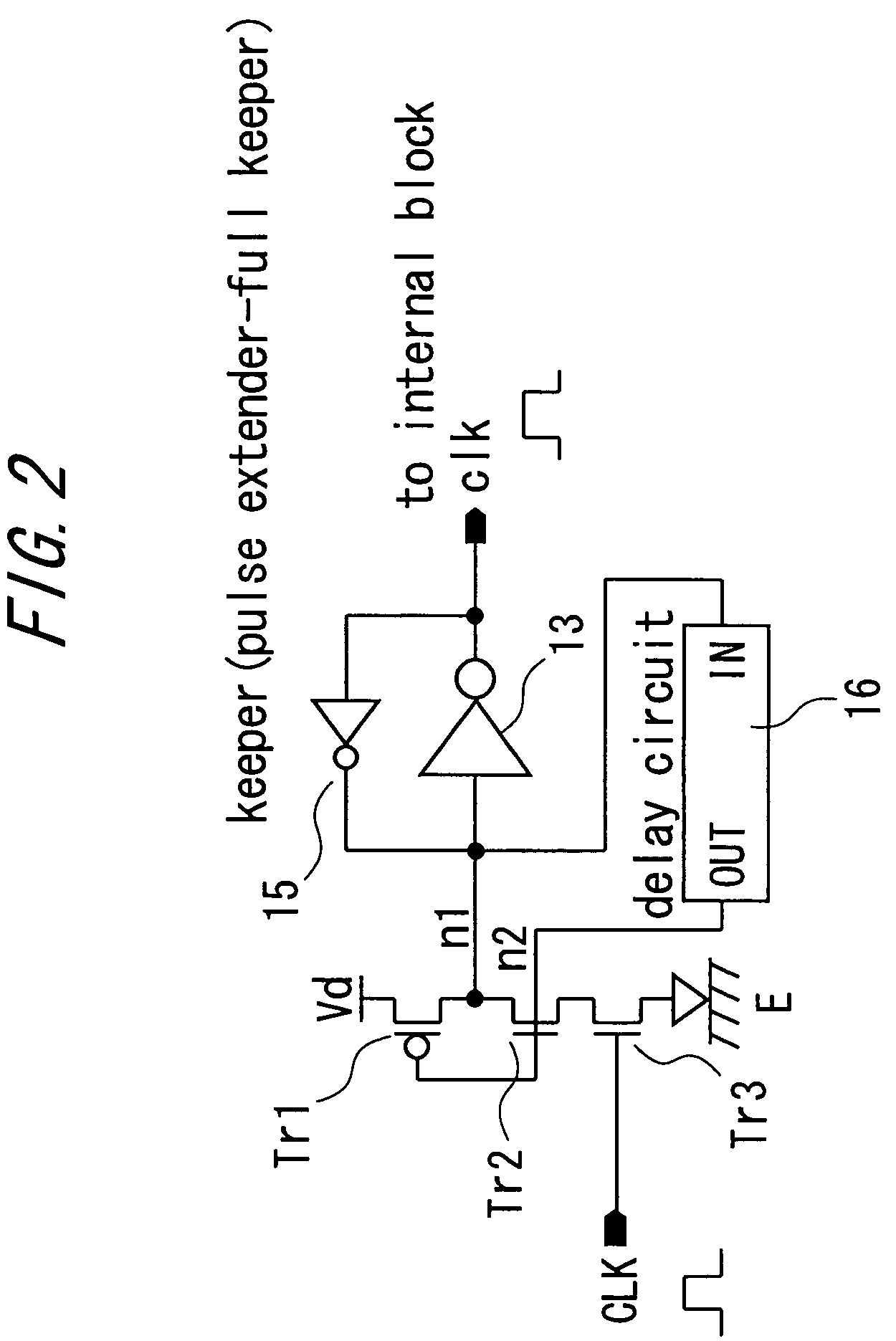
[0049]FIG. 2 shows the pulse generation circuit as a first embodiment of the present invention.

[0050]The pulse generation circuit 1 in the first embodiment is constructed of a P-type MOS (Metal Oxide Semiconductor) transistor Tr1, first and second N-type MOS transistors Tr2, Tr3, a delay circuit 16, an inverter 13 and a keeper 15.

[0051]A source electrode of the P-type MOS transistor Tr1 is connected to a first power source line. A drain electrode of the first N-type MOS transistor Tr2 is connected to a drain electrode of the P-type MOS transistor Tr1.

[0052]A drain electrode of the second N-type MOS transistor Tr3 is connected to the drain electrode of the first N-type MOS transistor Tr2, a gate electrode of the second N-type MOS transistor Tr3 is connected to an input line CLK to which the input pulse signal is inputted, and a source electrode thereof is connected to a second power source line. In this first embodiment, the first power source line is-a power source line supplied wit...

second embodiment

[0068]The first embodiment takes the configuration that the input pulse signal is inputted to the second N-type MOS transistor Tr3, and the output of the delay circuit 16 is inputted to the P-type MOS transistor Tr1 and to the first N-type MOS transistor Tr2 (corresponding to claim 1), however, another configuration shown in FIG. 6 is also available, wherein the layout of the N-type MOS transistors is exchanged (corresponding to claim 2).

[0069]Specifically, in the pulse generation circuit 1 in the second embodiment, the source electrode of the P-type MOS transistor Tr1 is connected to the first power source line, a drain electrode of a first N-type MOS transistor Tr4 is connected to the drain electrode of the P-type MOS transistor Tr1, and a gate electrode of the first N-type MOS transistor Tr4 is connected to the input line to which the input pulse signal is inputted. Further, a drain electrode of a second N-type MOS transistor Tr5 is connected to the drain electrode of the first N...

third embodiment

[0074]In the first embodiment discussed above, the input terminal of the delay circuit is connected to the drain electrode of the P-type MOS transistor Tr1 and to the drain electrode of the first N-type MOS transistor Tr2, i.e., to the node n1, however, the present invention is not limited to this connection. For example, in a third embodiment, as shown in FIG. 7, an input terminal of a delay circuit 12 is connected to the output line clk. This delay circuit 12 takes a configuration that an odd number of inverters are connected in series. Other configurations are the same as those in the first embodiment discussed above, and hence the repetitive explanations are omitted in a way that marks the same components with the same numerals and symbols.

[0075]Namely, in the pulse generation circuit 1 in the third embodiment, the voltage level of the node n1 is inverted by the inverter 13 and is thus inputted to the delay circuit 12, and consequently this voltage level is, after being inverted...


PUM


Abstract

Pulse generation circuit has a P-MOS transistor having a drain electrode connected to a first power source; a first N-MOS transistor having a drain electrode connected to the source electrode of the P-MOS transistor; a second N-MOS transistor having a drain electrode connected to the source electrode of the first N-MOS transistor, a gate electrode receiving an input pulse signal, and a source electrode connected to the second power source; a delay circuit having an input terminal connected to the source electrode of the P-MOS transistor and the drain electrode of the first N-MOS transistor and an output terminal connected to gate electrode of the P-MOS transistor and gate electrode of the first N-MOS transistor; an inverter input connected to the source electrode of the P-MOS transistor and the drain electrode of the second N-MOS transistor for outputting a generated pulse; and a keeper keeping voltage level to the inverter.

Description

CROSS-REFERENCE TO RELATED APPLICATION[0001]This is a continuation of Application PCT / JP2003 / 010295, filed on Aug. 13, 2003, now pending, the contents of which are herein wholly incorporated by reference.BACKGROUND OF THE INVENTION[0002]The present invention relates to a pulse generation circuit applied to generation etc. of a pulse of a clock in a circuit such as an LSI.[0003]FIGS. 18 through 21 are diagrams each showing an example of a conventional pulse generation circuit. The pulse generation circuit shown in FIG. 18 is constructed of a 2-input NAND circuit 11, a delay circuit 12 consisting of inverters provided at odd-numbered stages, and an inverter 13. When an input pulse signal (positive pulse) is inputted to this pulse generation circuit, this pulse is inputted to one input of the NAND circuit 11, and a negative pulse with a predetermined delay is inputted to the other input of the NAND circuit 11 via the delay circuit 12. Accordingly, an output of the NAND circuit 11 is ke...

Claims


Application Information

Patent Timeline
Patent Type & Authority Patents(United States)
IPC IPC(8): G05F1/04H03K3/00G06F1/08G06F1/10H03K3/033H03K5/04H03K5/06H03K5/13
CPCG06F1/04G06F1/08G06F1/10H03K5/06H03K2005/00293
Inventor IJITSU, KENJI
Owner FUJITSU LTD
Why Eureka
Try Eureka