
Constant gain nonlinear envelope tracking high efficiency linear amplifier

a linear amplifier, nonlinear envelope technology, applied in the direction of gain control, amplifier modification to reduce nonlinear distortion, transmission, etc., can solve the problems of low overall efficiency, large peak excursions in the rf signal carrier, signal requires conventional rf amplifiers that are costly and relatively inefficient, etc., to achieve constant supply voltage and constant gain

Active Publication Date: 2008-10-21
TAHOE RES LTD
View PDF35 Cites 122 Cited by
  • Summary
  • Abstract
  • Description
  • Claims
  • Application Information

AI Technical Summary

Benefits of technology

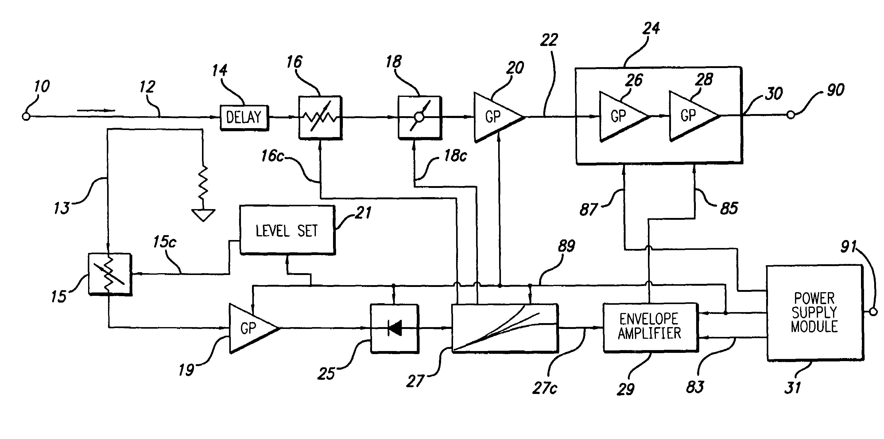
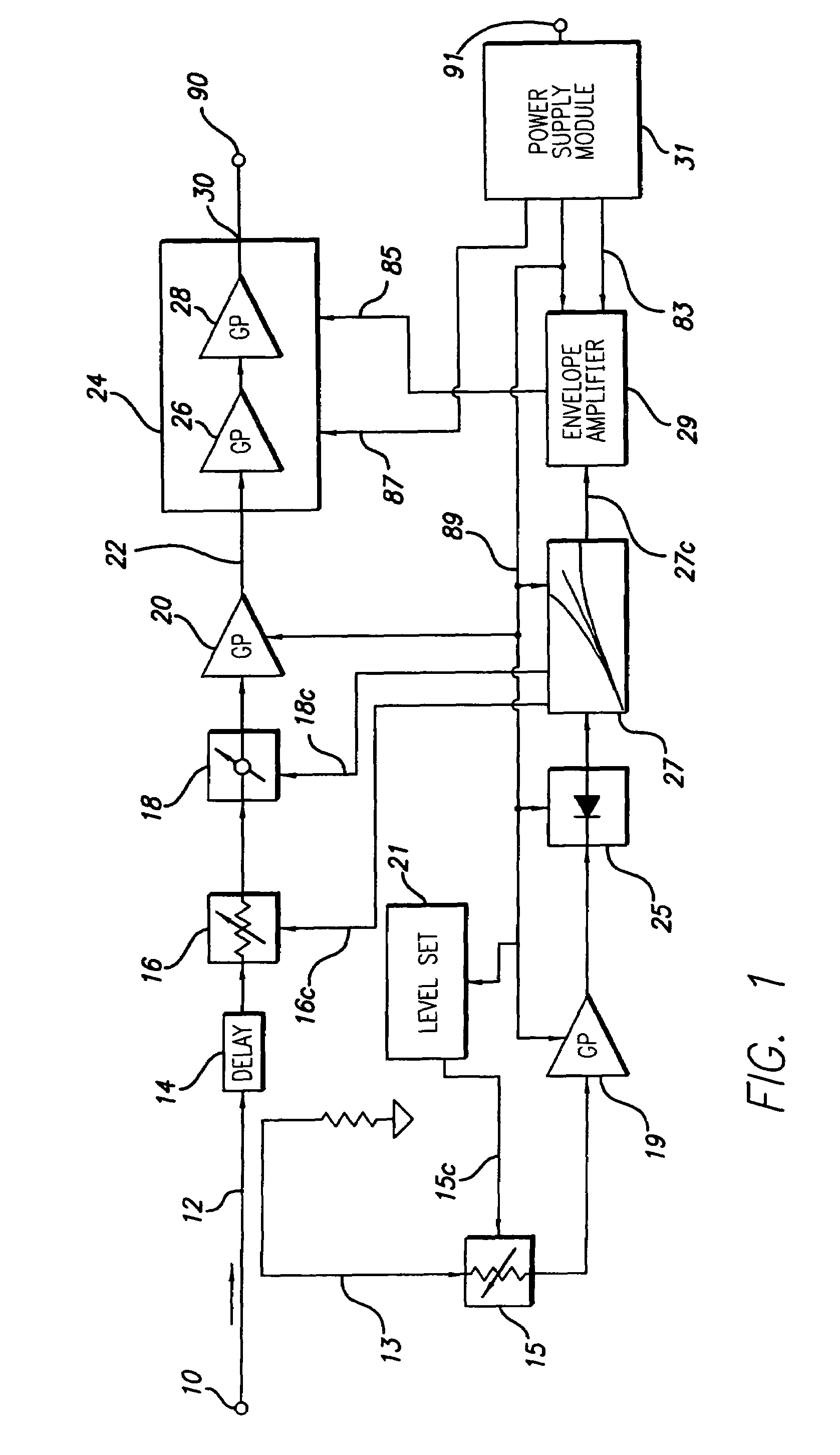
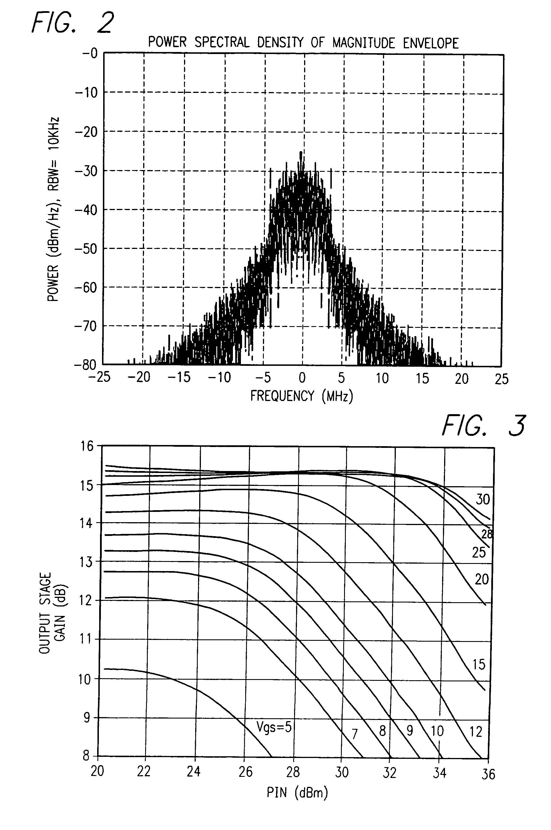
The present invention provides a power amplifier system and method for amplifying high frequency modulated signals with a dynamically varying envelope. The system and method include a power amplifier module with a saturation region, a DC power supply, an RF amplifier, a phase compensation circuit, and a variable power supply circuit. The variable power supply circuit provides a supply voltage that increases with the input signal power to maintain constant RF amplifier gain up to the beginning of the saturation region. The phase compensation circuit adjusts the phase of the input signal to compensate for phase variations due to the variable power supply. The system and method also include a DC power supply and a predistorter for controlling the phase adjustment. The method further includes detecting a signal related to the power of the input signal and controlling the DC power supply in response to the detected signal to maintain constant gain up to the beginning of the saturation region. The system and method also include adjusting the phase of the input signal with a continuously increasing phase adjustment in the higher power input signal region. The technical effects of the invention include maintaining constant RF amplifier gain and phase up to the beginning of the saturation region, compensating for phase variations due to the variable power supply, and adjusting the phase to compensate for phase variations introduced by controlling the supply voltage.

Problems solved by technology

The modulated sub carriers are then added up, thus causing large peak excursions in the RF signal carriers.
RF carriers modulated with large peak-to-average ratio signals require conventional RF amplifiers that are costly and relatively inefficient.
However, during most of the time, the average power output is only a small fraction of the peak power, resulting in low overall efficiency, typically below 10%.
While these prior EER approaches may offer viable efficiency enhancement solutions, they add additional complexity due to support circuits and diminished linearity over operating conditions.
Therefore, the desired combination of linearity and efficient operation, especially where large peak signals are present, has not yet been achieved.

Method used


Image

  • Constant gain nonlinear envelope tracking high efficiency linear amplifier
  • Constant gain nonlinear envelope tracking high efficiency linear amplifier
  • Constant gain nonlinear envelope tracking high efficiency linear amplifier

Examples


Embodiment Construction

[0022]The present invention is directed to improving the linearity and enhancing the efficiency of RF power amplifiers operated with signals having high dynamic range, and, more particularly, to an amplifier operating at microwave frequencies with high peak to average ratio input RF signals.

[0023]First the general principles and method of operation will be described. Intermodulation distortion stems from nonlinear amplitude and phase response characteristics inherent to high power devices when operated near maximum output power levels. The present invention addresses linearity and efficiency requirements by monitoring a detected input envelope waveform, processing it, and controlling supply voltages to power devices and adjusting the phase and amplitude of the incident RF signal so as to achieve the best possible AM-AM and AM-PM response possible, while achieving efficient performance.

[0024]More specifically, the RF input signal is detected by an envelope detector. The instantaneous...


PUM


Abstract

An envelope tracking radio frequency (RF) power amplifier having an adaptive envelope signal processing circuit is disclosed. An RF input voltage is sampled by the adaptive envelope signal processing circuit which provides control signals to the power supply which supplies voltages to RF power devices in order to simultaneously satisfy two operating conditions: a) provide best possible efficiency of the power amplifier stages depending on the input signal characteristics and b) provide compensation for RF transistor AM-AM and AM-PM distortion compensation across the power range. In particular, the voltage control provides for constant power amplifier gain across the input signal dynamic range, thus minimizing power amplifier amplitude distortions and extending the useful power amplifier linear dynamic range up to saturation point. The power amplifier thus exhibits better linearity and efficiency than offered by conventional techniques and topologies.

Description

RELATED APPLICATION INFORMATION[0001]The present application claims priority under 35 USC Section 119(e) to provisional application Ser. No. 60 / 560,889 filed Apr. 9, 2004, the disclosure of which is incorporated herein by reference in its entirety.FIELD OF THE INVENTION[0002]The invention relates in general to power amplifiers and, more particularly, to high efficiency power amplifier circuits. More particularly, the invention relates to amplifiers operating at microwave frequencies with high peak to average ratio input RF signals.BACKGROUND OF THE INVENTION[0003]Modern cellular communication systems employ RF power amplifiers in their base stations, in order to provide communication means to subscribers. To achieve maximum utilization of available spectrum power amplifiers are required to amplify multiple Radio Frequency (RF) carriers. In addition to multiple RF carriers, each RF carrier employs a digital coding scheme such as Code Division Multiple Access (CDMA), which allows for ...

Claims


Application Information

Patent Timeline
Patent Type & Authority Patents(United States)
IPC IPC(8): H04B1/04H04Q7/20H01Q11/12H03F1/00H03F1/02H03F1/32H03G3/00
CPCH03F1/0227H03F1/32H03G3/004H04B1/0483H03F2200/102H04B2001/045H03F1/02H03F3/24
Inventor MASLENNIKOV, NIKOLAIGURVICH, MARKRABINOVICH, ALEXANDER
Owner TAHOE RES LTD
Learn More