Copper to aluminum bimetallic termination

a technology of aluminum bimetallic termination and copper, which is applied in the direction of electrically conductive connections, coupling device connections, electrical apparatus, etc., can solve the problems of aluminum conductors that are undesirable, aluminum also suffers from other forms of corrosion, and heat is likely to occur, so as to reduce oxidation corrosion

Inactive Publication Date: 2008-08-19
TYCO ELECTRONICS BRASIL
View PDF7 Cites 11 Cited by
  • Summary
  • Abstract
  • Description
  • Claims
  • Application Information

AI Technical Summary

Benefits of technology

[0012]In another embodiment, the invention is directed to a method of reducing oxidation corrosion in a bimetallic electrical connection. The method includes the steps of providing an annular copper connector body and an annular brass insert portion; coating the connector body and the insert portion with a layer of tin; perforating a surface of the insert portion with a plurality of apertures; inserting the insert portion into the connector portion with a friction fit; inserting an aluminum cable end into the insert portion; crimping the aluminum cable end, the connector body, and the insert portion together to form a sealed electrical connection is between the aluminum cable and the copper connector body; attaching the crimped connector body to a copper electrical bus bar to form a bimetallic junction having a tin exterior layer disposed between a copper bus bar and an end of the aluminum cable when the crimped connector is attached to the copper bus bar.

Problems solved by technology

Major problems are related to oxide film existent on aluminum wire surfaces, which are difficult to break and to establish a good electrical connection and the galvanic corrosion process while both aluminum and copper conductors are in contact.
This corrosion is typically caused where the copper and aluminum interface is exposed to the outdoor environment, or to other corrosive environment.
Conversely, aluminum conductors have an undesirable characteristic of forming a high resistance film of aluminum oxide on the outside of the conductor when it is exposed to the air.
Unless the connection is properly prepared, a high resistance contact is the result and heating is likely to occur.
In addition, aluminum also suffers from other forms of corrosion, e.g., creep corrosion.

Method used


Image

  • Copper to aluminum bimetallic termination
  • Copper to aluminum bimetallic termination
  • Copper to aluminum bimetallic termination

Examples


Embodiment Construction

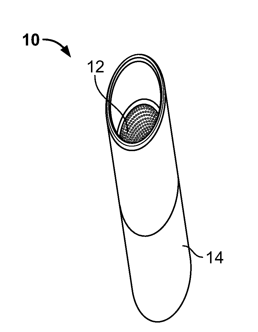
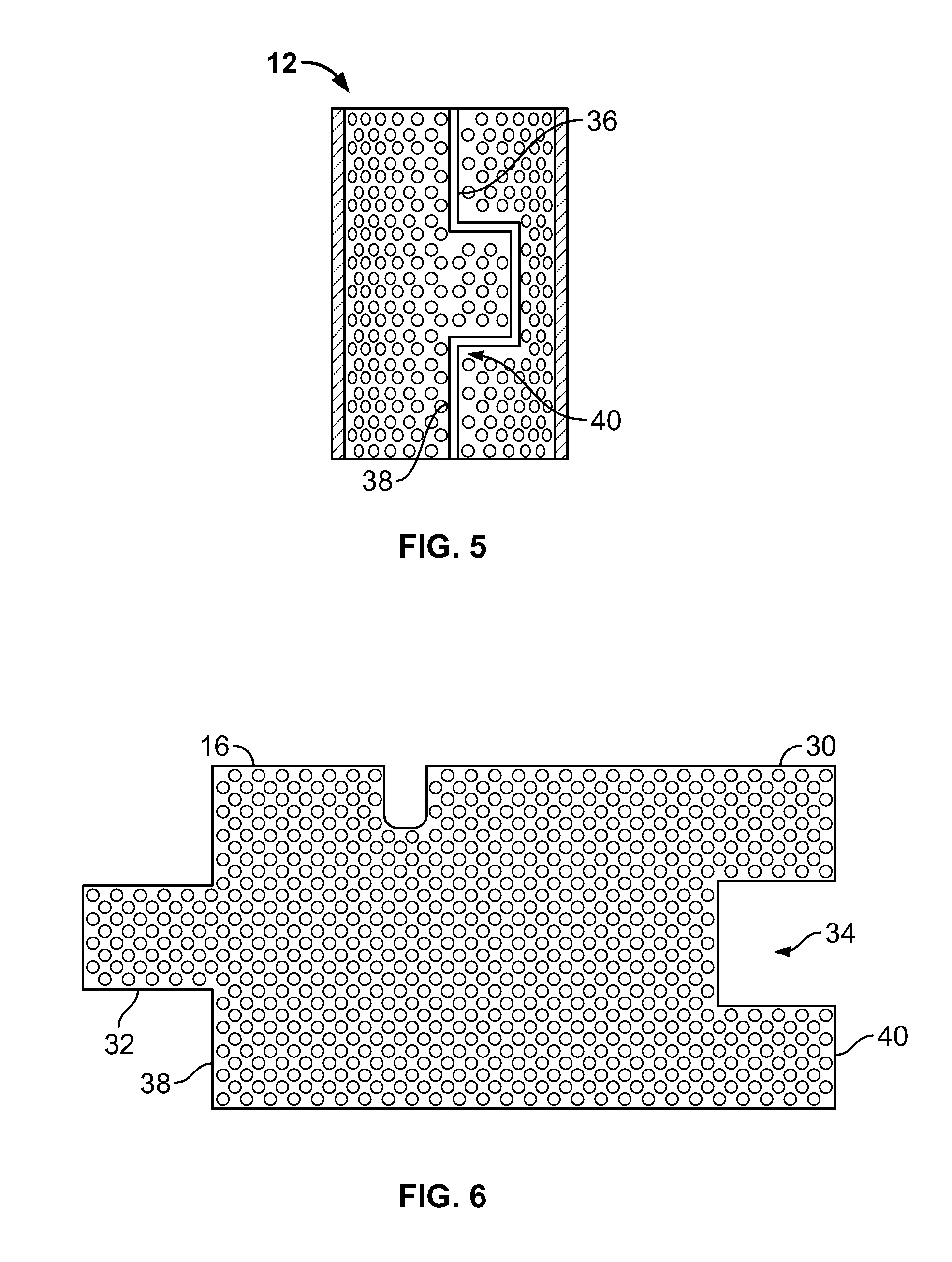
[0022]Referring to FIGS. 1-6, a crimp-type connector 10 is made up of a hollow copper or tin-clad copper body portion 14 and a tin-clad brass insert portion 12. The insert portion 12 is perforated with micro holes 16.

[0023]The insert portion 12 fits into the inner dimension of the hollow body portion 14. The insert portion 12 is friction fit within the body portion 14 so as to remain within the interior of the body portion 14 when a multi-stranded cable end is inserted within the connector 10. In one embodiment, the insert portion 12 has length that is generally less than the length of the body portion 14. In one embodiment, the body portion 14 extends or overlaps the ends of the insert portion 12 at both ends 18, 20, to form a slightly larger inner diameter at either end. The body portion 14 may have a beveled or tapered edge 22 at either or both ends, to facilitate insertion of the termination into, e.g., a lug terminal on a power bus 24. The slightly larger inner diameter at eith...


PUM

PropertyMeasurementUnit
diameteraaaaaaaaaa
diameteraaaaaaaaaa
electrical currentaaaaaaaaaa

Abstract

The connector includes an annular connector body that is substantially comprised of copper, and an annular insert portion made of brass and clad with tin. Apertures are made through the wall of the insert portion. The insert portion is configured to have an exterior frictionally fit within the connector body. Inserting a stranded aluminum cable into the annular insert portion and crimping the connector body, the insert portion and the cable, causes the outer strands of the stranded aluminum cable to be extruded through the plurality of apertures, removing oxide film on the exterior surface of the aluminum cable and forming a sealed electrical connection between the aluminum cable and the copper connector body.

Description

FIELD OF THE INVENTION[0001]The present invention is directed to an electrical connector, and more specifically to an electrical connector that includes a copper body and a tin-clad liner insert to facilitate electrical connections between copper and aluminum circuit elements.BACKGROUND OF THE INVENTION[0002]Major problems are related to oxide film existent on aluminum wire surfaces, which are difficult to break and to establish a good electrical connection and the galvanic corrosion process while both aluminum and copper conductors are in contact.[0003]Electrical power distribution systems frequently include a mixture of aluminum and copper conductors at various portions of the distribution system. When used in contact with one another, aluminum and copper conductors, a corrosion process erodes the aluminum cable. This corrosion is typically caused where the copper and aluminum interface is exposed to the outdoor environment, or to other corrosive environment.[0004]Copper cables ha...

Claims


Application Information

Patent Timeline
Patent Type & Authority Patents(United States)
IPC IPC(8): H01R4/10
CPCH01R4/20H01R13/03H01R4/62Y10T29/49181
Inventor LASALVIA, JOSE ALEXANDREFUZETTI, VAGNER
Owner TYCO ELECTRONICS BRASIL
Why Eureka
Try Eureka