Piezoelectric element, ink jet recording head and producing method for piezoelectric element

a piezoelectric element and ink jet technology, applied in piezoelectric/electrostrictive/magnetostrictive devices, piezoelectric/electrostriction/magnetostriction machines, printing, etc., can solve the problems of increased leak current or deterioration of piezoelectric characteristics, increased leak current, electrical characteristics deterioration, etc., to achieve large displacement and large remnant polarization

Active Publication Date: 2008-07-15
CANON KK +1
View PDF14 Cites 1 Cited by
  • Summary
  • Abstract
  • Description
  • Claims
  • Application Information

AI Technical Summary

Benefits of technology

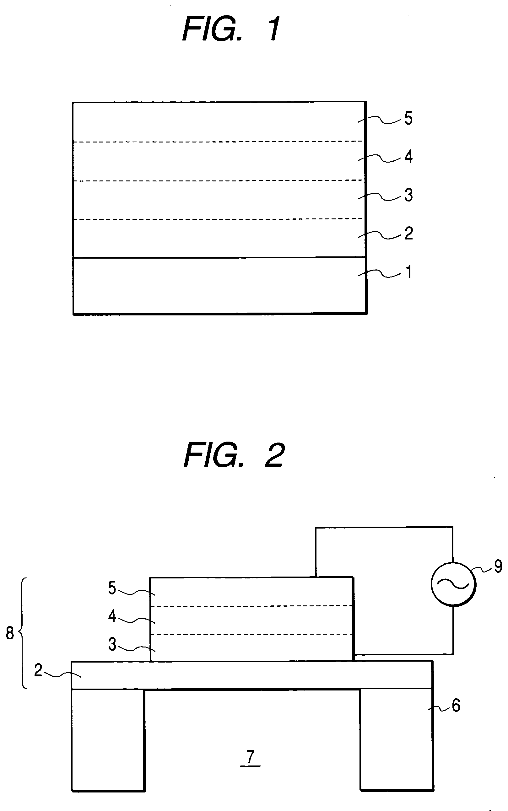
[0011]An object of the present invention is to provide a piezoelectric element in which a matching and an adhesion are improved between an upper electrode, a piezoelectric film, a lower electrode and a vibrating plate, to provide a long service life while maintaining satisfactory dielectric constant and electrical characteristics, an ink jet recording head utilizing such piezoelectric element, and a method for producing a piezoelectric element.
[0032]In producing a piezoelectric element by the sol-gel method, the present invention eliminates junction interfaces in the upper electrode / piezo-electric film / lower electrode / vibrating plate structure, thereby allowing to provide a piezoelectric element and an ink jet recording head showing a large remnant polarization and capable of providing a large displacement.

Problems solved by technology

Such irregularities may cause an interfacial roughness to an upper electrode, thereby resulting in an increased leak current or a deterioration in the piezoelectric characteristics.
Also a prior piezoelectric element employ, as a lower electrode, a precious metal such as Ru or Pt or an oxide thereof, and an interfacial mismatching between the piezoelectric film and the lower electrode may cause a deterioration of electrical characteristics, such as an increased leak current or a loss in the dielectric breakdown resistance.
Also in a piezoelectric element of a prior configuration, a perovskite type oxide such as barium titanate, strontium titanate or calcium titanate employed as the lower electrode may result in a deterioration of characteristics, particularly a displacement amount, of the piezoelectric film, because of a higher resistance of the electrode in comparison with the case of the precious metal.
Furthermore, in the piezoelectric element of the prior configuration, an in-plane stress may be concentrated on a junction interface of a vibrating plate and a lower electrode, thereby leading to a peeling in a thermal treatment step in the manufacture or when the element is driven.

Method used


Image

  • Piezoelectric element, ink jet recording head and producing method for piezoelectric element
  • Piezoelectric element, ink jet recording head and producing method for piezoelectric element
  • Piezoelectric element, ink jet recording head and producing method for piezoelectric element

Examples


example 1

[0086]For forming a vibrating plate, the liquid A mentioned above was coated with a spin coater on a silicon single crystal substrate and dried for 5 minutes on a hot plate of 150° C. This operation was repeated 6 times to obtain a vibrating plate precursor of a thickness of about 5 μm. On the surface thereof, the liquid C mentioned above was similarly coated with a spin coater. The coated film was dried for 5 minutes on a hot plate of 150° C. to obtain a lower electrode precursor. Then on the surface thereof, the liquid F was similarly coated with a spin coater as a piezoelectric film, and dried for 5 minutes at 250° C. to obtain a piezoelectric film precursor. The vibrating plate precursor, the lower electrode precursor and the piezoelectric film precursor thus obtained were simultaneously sintered in an electric oven of 700° C. for 10 minutes. Thereafter the coating, drying and sintering of the liquid F were repeated 10 times. Then the liquid F were coated and dried to obtain a p...

example 2

[0087]For forming a vibrating plate as in Example 1, the liquid B mentioned above was coated with a spin coater on a silicon single crystal substrate and dried for 5 minutes on a hot plate of 300° C. This operation was repeated 10 times to obtain a vibrating plate precursor of a thickness of about 4 μm. On the surface thereof, the liquid D mentioned above was similarly coated with a spin coater and was dried for 5 minutes at 150° C. to obtain a lower electrode precursor. Then the vibrating plate precursor and the lower electrode precursor were simultaneously sintered for 10 minutes at 700° C. Then the liquid D was further coated and dried for 5 minutes at 100° C. to obtain a lower electrode precursor. Then on the surface thereof, the liquid E was coated with a spin coater and dried for 5 minutes at 100° C. to obtain a piezoelectric film precursor. The lower electrode precursor and the piezoelectric film precursor were simultaneously sintered in an electric oven of 700° C. for 10 min...


PUM


Abstract

A piezoelectric element including a vibrating plate, a lower electrode, a piezoelectric film and an upper electrode laminated in this order, wherein the lower electrode, the upper electrode and the piezoelectric film are formed by a perovskite type oxide while the vibrating plate is formed by a metal oxide, and a junction interface is substantially absent between the vibrating plate and the lower electrode, between the lower electrode and the piezoelectric film and between the piezoelectric film and the upper electrode.

Description

BACKGROUND OF THE INVENTION[0001]1. Field of the Invention[0002]The present invention relates to a piezoelectric element having a metal oxide ferroelectric film applicable to various dielectric devices by electric and / or optical properties, an ink jet recording head utilizing the same and a producing method for a piezoelectric element.[0003]2. Related Background Art[0004]A piezoelectric element is constituted of a crystalline piezoelectric ceramic material of a ferroelectric or paraelectric property. The piezoelectric ceramic material generally has a two-component composition principally constituted of lead zirconate titanate (hereinafter represented as “PZT”), or a three-component composition in which a third component is added to PZT of the two-component composition. A ferroelectric material utilizing a two-component PZT is described in Applied Physics Letters, 1991, vol. 58, No. 11, pp 1161-1163.[0005]A ferroelectric thin film of such metal oxide type can be prepared, for example...

Claims


Application Information

Patent Timeline
Patent Type & Authority Patents(United States)
IPC IPC(8): B41J2/045H01L41/00B41J2/055B41J2/135B41J2/14B41J2/16H01L41/09H01L41/187H01L41/22H01L41/318H02N2/00
CPCB41J2/14233B41J2/14298B41J2/161B41J2/1617B41J2/1629H01L41/0973H01L41/0805H01L41/318H01L41/0478B41J2/1645H01L41/0477H10N30/878H10N30/877H10N30/1051H10N30/2047H10N30/078
Inventor KUBOTA, MAKOTOKOBAYASHI, MOTOKAZUERITATE, SHINJISUZUKI, HISAOUCHIDA, FUMIOSHIMIZU, CHIEMIMAEDA, KENJI
Owner CANON KK
Why Eureka
Try Eureka