Vacuum tube circuit

a vacuum tube circuit and circuit technology, applied in the field can solve the problems of large power consumption of vacuum tube circuits in the proposed technology, and achieve the effects of low voltage, low power consumption, and high density

Active Publication Date: 2008-07-08
KORG
View PDF6 Cites 4 Cited by
  • Summary
  • Abstract
  • Description
  • Claims
  • Application Information

AI Technical Summary

Benefits of technology

[0005]It is another object of the present invention to provide a vacuum tube circuit with low voltage and low power consumption which fits to a battery operation.
[0006]It is a further object of the present invention to provide a vacuum tube circuit which can be implemented with high density, small size and with high reliability.

Problems solved by technology

Thus, the vacuum tube circuit in the proposed technology consumes a relatively large amount of power.

Method used


Image

  • Vacuum tube circuit
  • Vacuum tube circuit
  • Vacuum tube circuit

Examples


first embodiment

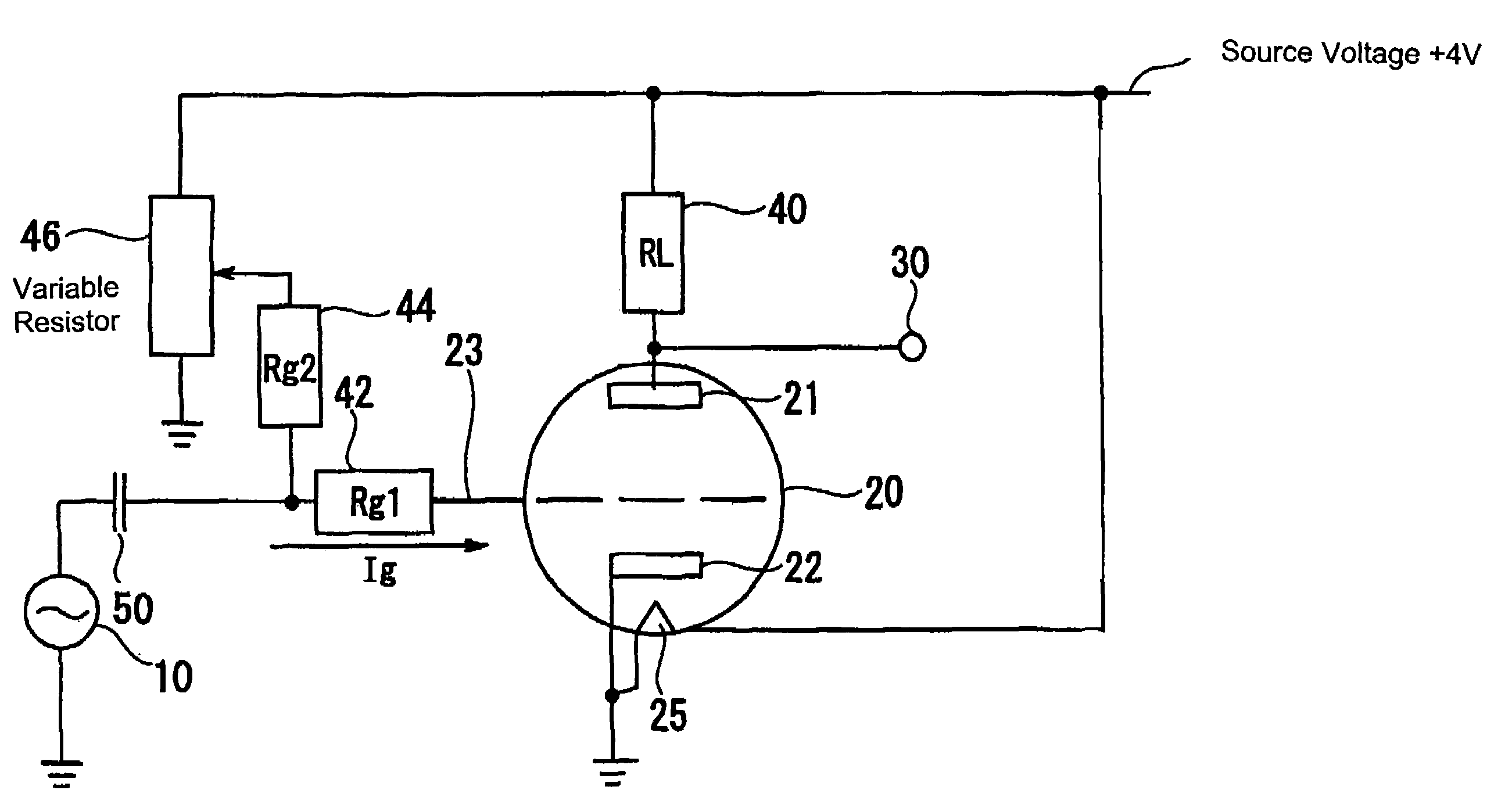
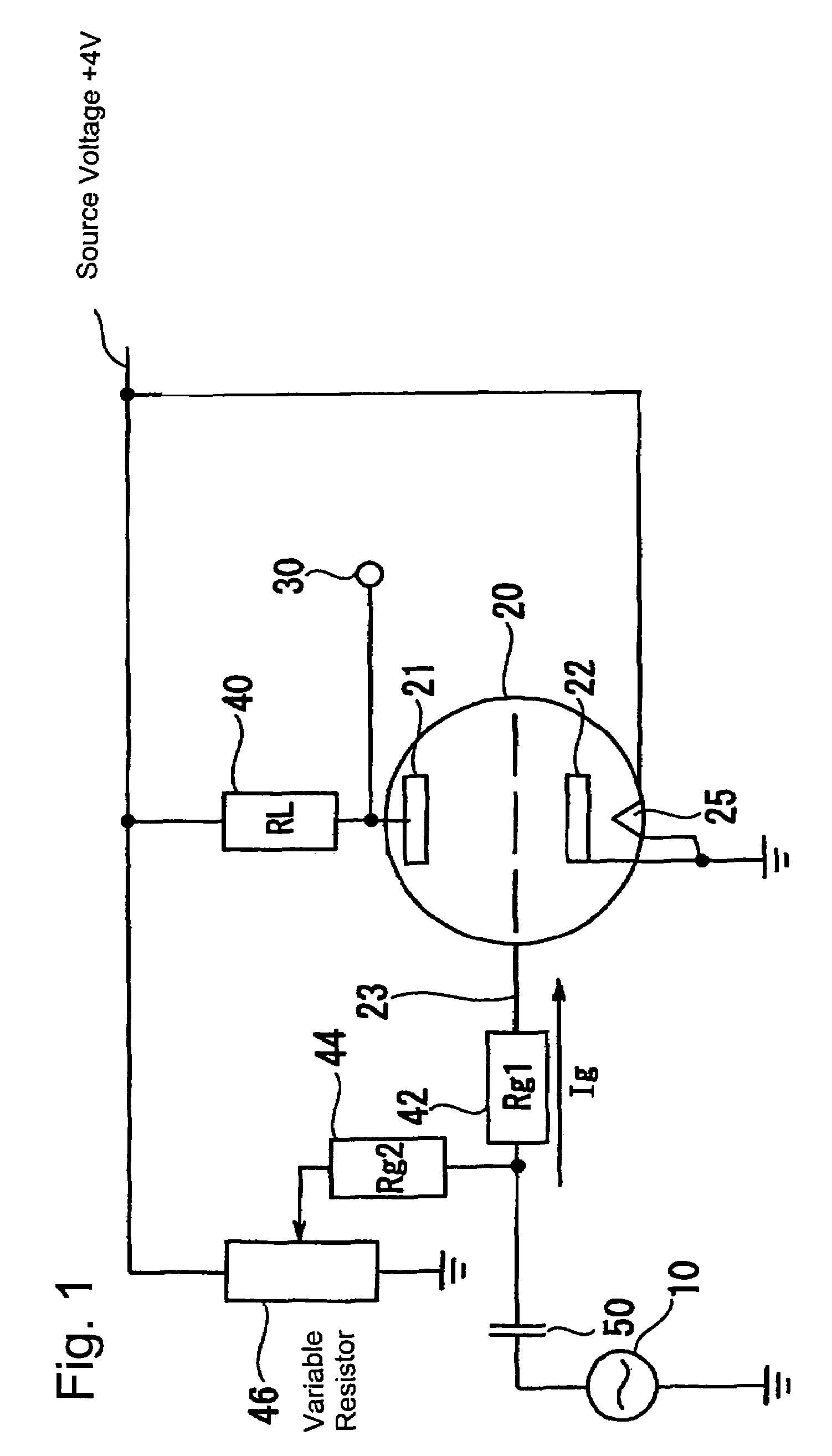
[0014]FIG. 1 shows a configuration in the first embodiment of the vacuum tube circuit. In this example, a cathode terminal 22 of the vacuum tube 20 is connected to the ground, and a heater 25 for emitting the electrons from the cathode terminal 22 is provided with a low source voltage of +4V, for example. One end of a resistor (RL) 40 is connected to a plate terminal 21 of the vacuum tube 20 which receives the electrons emitted from the cathode 22. The source voltage +4V is also supplied to the other end of the resistor (RL) 40. Further, one end of a resistor (Rg1) 42 is connected to a grid terminal 23 of the vacuum tube 20.

[0015]A signal source 10 for generating an audio signal is connected to the other end of the resistor (Rg1) 42 through a capacitor 50. One end of a resistor (Rg2) 44 is also connected to the other end of the resistor (Rg1) 42. The other end of the register (Rg2) 44 is connected to a variable resistor (voltage divider) 46. The source voltage +4V is also supplied t...

second embodiment

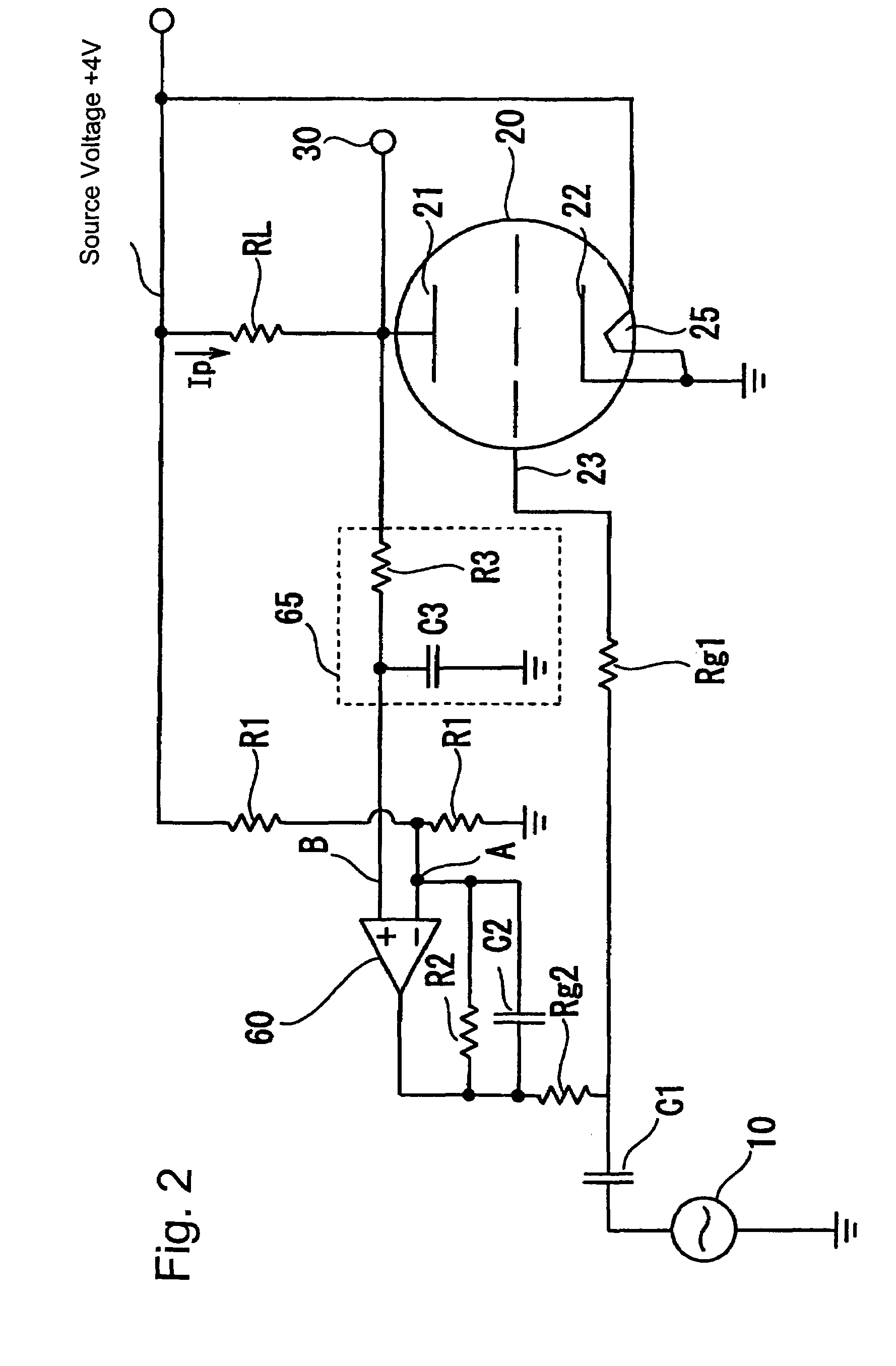
[0022]The second embodiment of the present invention is characterized by incorporating a bias control circuit which controls an output bias voltage so that the average value (bias voltage) of the amplified signal at the output terminal 30 becomes a predetermined level, for example, half of the voltage value of the source voltage.

[0023]FIG. 2 shows an example of circuit structure of the second embodiment in which the component identical to that of FIG. 1 is denoted by the same reference number. In this example, the cathode terminal 22 of the vacuum tube 20 is connected to the ground, and the heater 25 for emitting the electrons from the cathode terminal 22 is provided with a low source voltage of +4V, for example. One end of the resistor (RL) 40 is connected to the plate terminal 21 of the vacuum tube 20 which receives the electrons emitted from the cathode 22. The source voltage +4V is also supplied to the other end of the resistor (RL) 40. Further, one end of the resistor (Rg1) 42 ...


PUM


Abstract

A vacuum tube circuit is capable of amplifying an input signal with use of a low source voltage. Ordinarily, the amount of electrons released from a cathode which is heated by a heater is small since a voltage supplied to the heater is low. In the vacuum tube circuit disclosed here, a positive voltage is supplied to a grid terminal, which more effectively attracts the emitted electrons, thereby increasing the amount of electrons arriving at the plate terminal passing through the grid. As a result, a grid current and a plate current flow in the vacuum tube circuit, which achieves an operation for amplifying an input signal from a signal source.

Description

FIELD OF THE INVENTION[0001]The present invention relates to a circuit for using a vacuum tube having a cathode, a plate, and a grid and provided with a heater for emitting electrons from the cathode, and more particularly, to a vacuum tube circuit which is able to amplify an input signal with use of a low source voltage and a positive grid voltage.BACKGROUND OF THE INVENTION[0002]Various circuits using an amplifying effect of a vacuum tube are proposed in various fields. Traditionally, in order to fulfill the amplifying effect of the vacuum tube, a rated voltage is supplied to a heater to flow a large current therethrough to emit electrons from the cathode of the vacuum tube. An amount of current flowing toward the plate of the vacuum tube caused by the emitted electrons is controlled by a negative voltage supplied to the grid terminal. In addition, in order to extract a large amount of controllable plate current, unlike the conventional controlling method of the vacuum tube, a met...

Claims


Application Information

Patent Timeline
Patent Type & Authority Patents(United States)
IPC IPC(8): H03G3/00H03F3/02H03F1/04H03F1/30H03F3/183H03G3/06
CPCH03F1/04H03F1/30H03F3/02H03G3/06H03F3/183H03F2200/21H03F2200/264H03F2200/513
Inventor MIEDA, FUMIO
Owner KORG
Why Eureka
Try Eureka