
Method and apparatus for load balancing in a virtual private network

a virtual private network and load balancing technology, applied in data switching networks, frequency-division multiplexes, instruments, etc., can solve the problems of inefficient load balancing of conventional vpn concentrators, inability to efficiently support conventional vpn concentrators, and inability to efficiently distribute existing connections or future incoming connections, etc., to achieve low load and balance load

Active Publication Date: 2008-05-20
CISCO TECH INC
View PDF23 Cites 44 Cited by
  • Summary
  • Abstract
  • Description
  • Claims
  • Application Information

AI Technical Summary

Benefits of technology

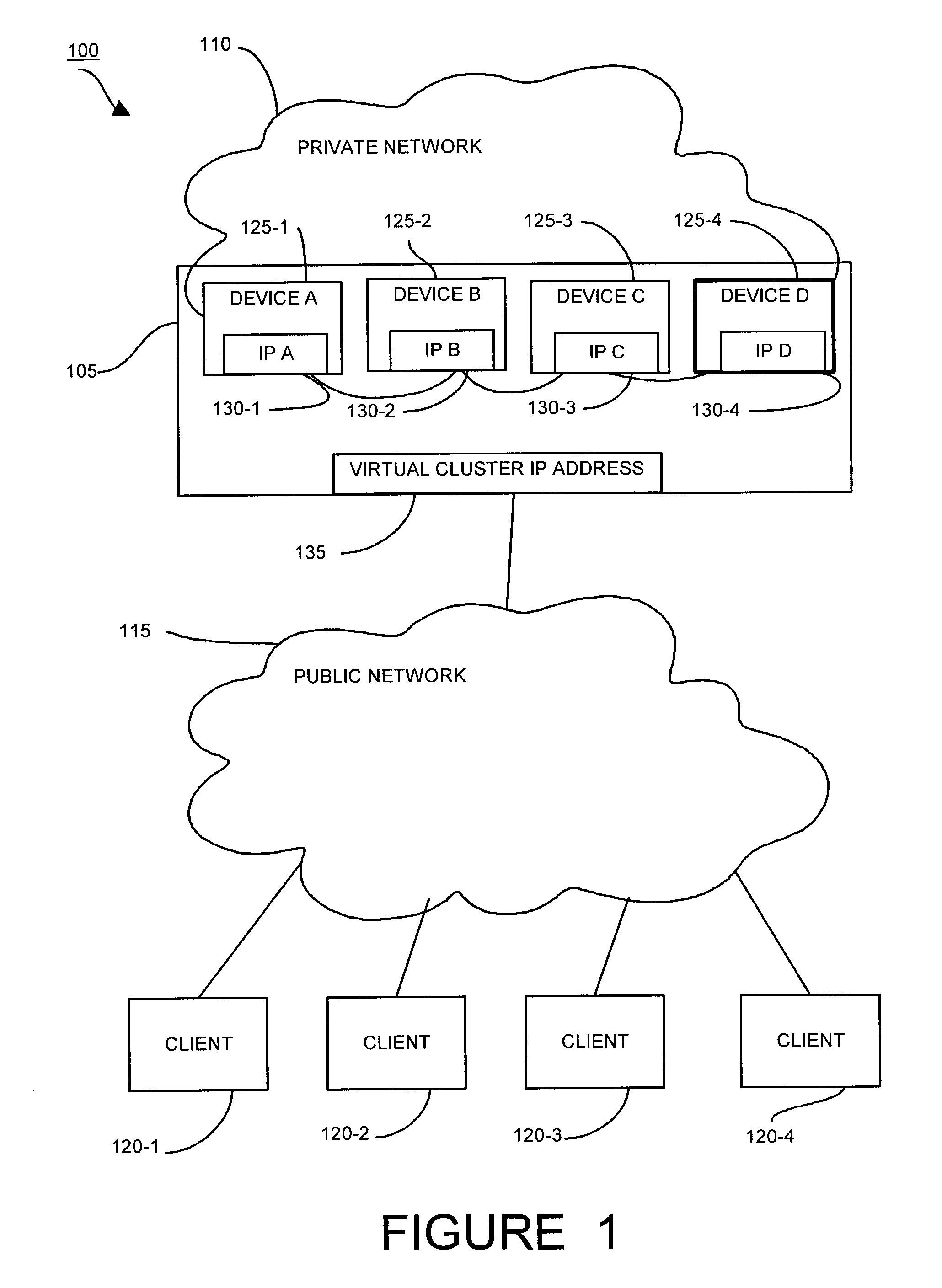
[0006]According to embodiments of the invention, a VPN virtual cluster has a plurality of concentrators accessible to clients through a single cluster IP address. The concentrators have one master concentrator to take client requests and distribute the client requests among the concentrators in the cluster. Each concentrator has a unique IP address, however each client knows only the cluster IP address used for the initial connection request. When a client request arrives at the VPN concentrator cluster, the master concentrator, which responds to requests directed to the cluster IP address, selects a concentrator from the cluster to handle the request. The master concentrator sends the unique IP address of the selected concentrator to the client for connection to the central site. The master concentrator can track load in the cluster and monitor which concentrators are operational and which are not. If the master concentrator fails, embodiments of the invention provide a mechanism to allow a new master concentrator to take over. The master concentrator provides load balancing and the shared connections among a cluster of concentrators provides redundancy that enhances concentrator availability.
[0022]In another embodiment of the invention, the initial client connection request is an IKE request and the method further includes negotiating authentication and encryption policies with the client in response to the IKE request. The method further includes transmitting to the client the address of the selected concentrator device, the device to handle the VPN connection, via an IKE notify payload message. In this way, the master device creates a secure connection between the virtual cluster and the client.

Problems solved by technology

Conventional VPN concentrator technology suffers from a variety of difficulties.
As an example, conventional VPN concentrators do not efficiently support load balancing.
Conventional VPN technology does not provide an efficient mechanism to distribute existing connections or future incoming connections to other VPN concentrators.
The problems created by this are increased latency and, in some situations, overloading of the concentrator.
This conventional configuration also introduces risk in that if that one concentrator fails, many clients lose the ability to connect to the central site because the clients have no alternative means of discovering another concentrator with which to establish a connection.

Method used


Image

  • Method and apparatus for load balancing in a virtual private network
  • Method and apparatus for load balancing in a virtual private network
  • Method and apparatus for load balancing in a virtual private network

Examples


first embodiment

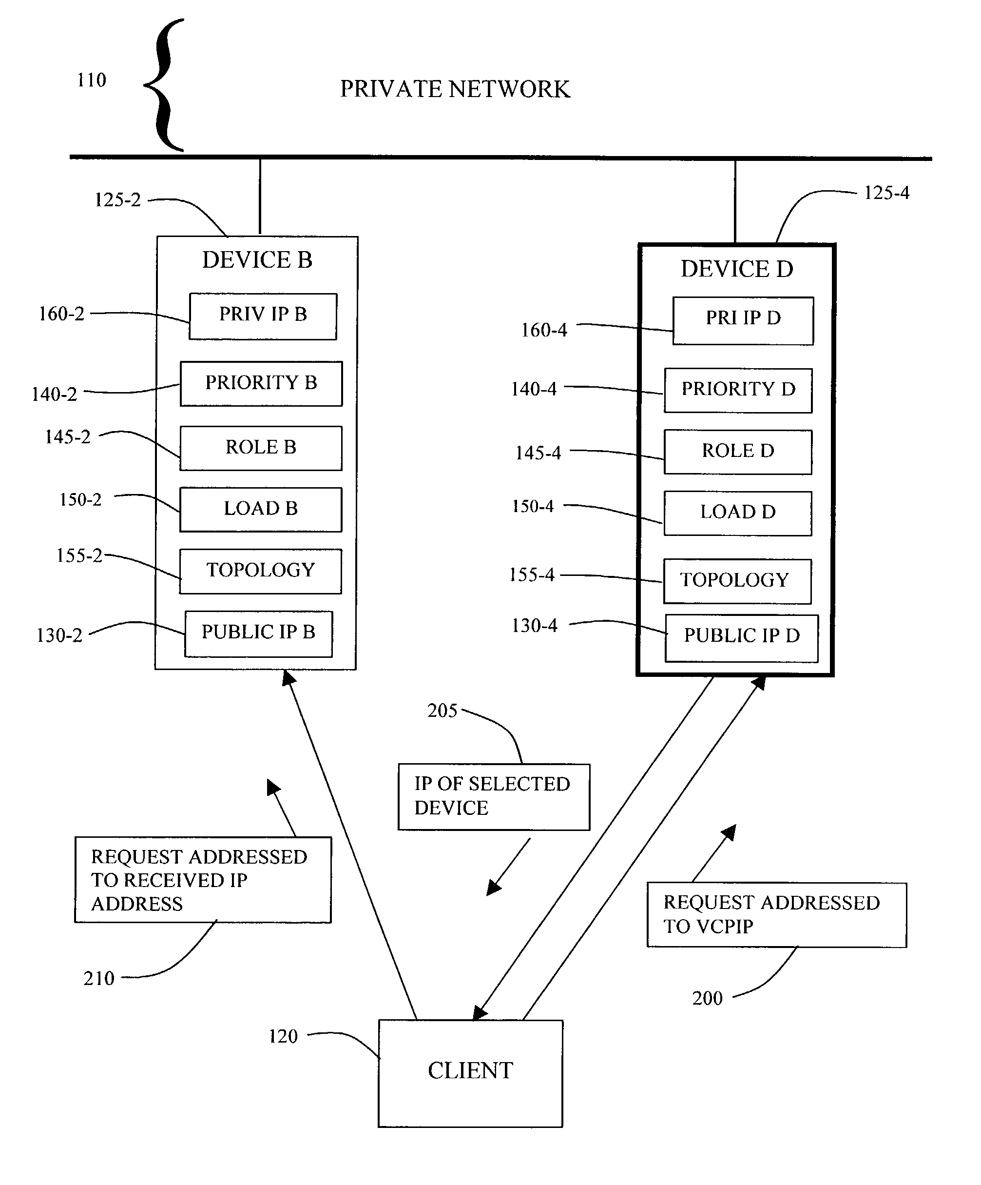
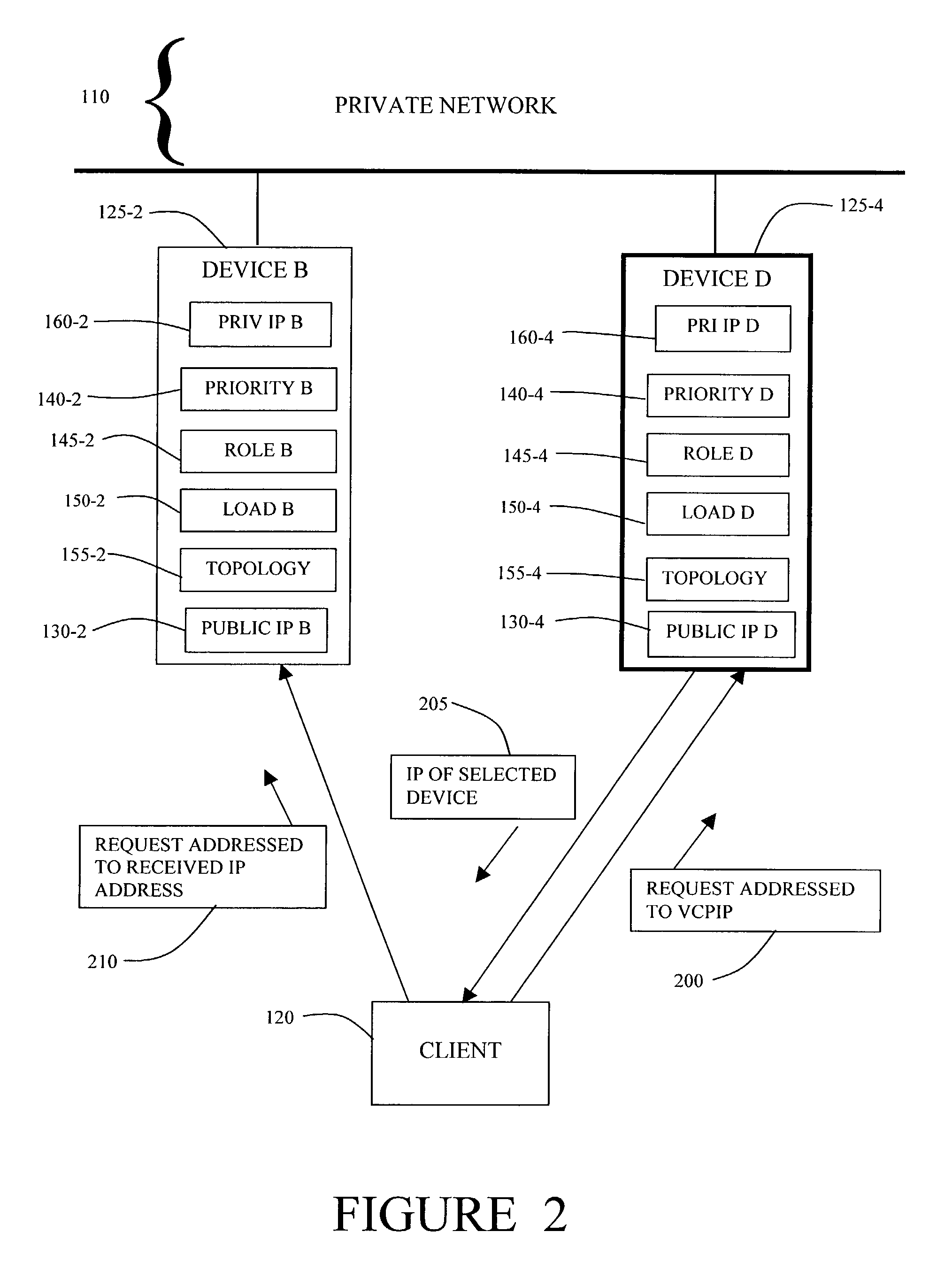
[0041]In the invention, when the client 120 initiates a connection to the private network 110, the client 120 transmits a initial request 200 addressed to the VCPIP 135.

[0042]Device D 125-4, as master device, responds to the request 200 addressed to the VCPIP 135. Device D 125-4 accepts the client request 200 and determines, based on the status and load of each device, which device in the VPN cluster 105 should handle the client request 200. The mechanism of this determination will be described below. In this example, Device D 125-4 is aware that Device B 125-2 is operational and that the load on Device B 125-2 is low compared to other devices in the cluster 105. Device D 125-4 selects Device B 125-2 to handle the client request 200. Device D 125-4 then transmits a return message 205 to the client 120 containing the IP address of the device selected by Device D 125-4. That is, Device D 125-4 transmits IP B 130-2 in the return message 205 to the client 120.

[0043]The client 120 addres...

second embodiment

[0044]In the invention, the initial request 200 initiates an Internet Key Exchange (IKE) negotiation with the master device 125-4. IKE is an Internet Engineering Task Force recommended protocol for secure network communications. IKE is based on a frame work protocol called Internet Security Association and Key Management Protocol (ISAKMP) and implements the Oakley key exchange. IKE is therefore also known as ISAKMP / Oakley. In the IKE negotiation, the client 120 and the master device, Device D 125-4, negotiate encryption and authentication policies.

[0045]The master device 125-4, at the completion of the IKE Phase 1 negotiation, sends an encrypted IKE notify payload with the IP address of the concentrator selected to handle the client's communication with the VPN.

[0046]In the second embodiment of the invention, the client 120, after receiving the IKE notify payload from the master device 125-4, initiates an IKE negotiation for encryption and authentication with the selected device, De...


PUM


Abstract

In a virtual private network, a plurality of concentrators form an interface to provide client / remote site access to a private network over a public network. The plurality of concentrators are grouped into a virtual cluster. Each concentrator in the virtual cluster has an IP address and the virtual cluster has a virtual IP address. In operation, one of the plurality of concentrators assumes the virtual IP address and acts as the master device in the cluster. When a client attempts a connection to the private network, the client addresses an initial request to the virtual IP address. The master device responds to the client request by transmitting to the client the IP address of a concentrator in the cluster selected to handle the connection.

Description

CROSS REFERENCE TO RELATED APPLICATIONS[0001]This application claims the benefit of priority under 35 U.S.C. 119(e) to U.S. Provisional Application Ser. No. 60 / 369,280, filed Apr. 2, 2002 and entitled “Methods and Apparatus for Operating a Virtual Private Network,” the teachings of which are hereby incorporated by reference in their entirety.BACKGROUND OF THE INVENTION[0002]A virtual private network (VPN) is a type of private network constructed by using public network infrastructure to connect divergent nodes. An example of a VPN uses virtual connections or tunnels routed through the Internet between a company's private central network and a remote site or to a remote employee on the road or working from home.[0003]In a VPN, one or more concentrators provide remote clients with a plurality of points of access to the central server. A concentrator is a type of multiplexor that combines multiple channels onto a single transmission medium in such a way that all the individual channels...

Claims


Application Information

Patent Timeline
Patent Type & Authority Patents(United States)
IPC IPC(8): G06F15/16G01R31/08H04L12/26H04L1/00H04J3/14G06F15/177G06F3/00G06F5/00H04J1/16G08C15/00G06F15/173G06F11/00
CPCH04L12/4641H04L43/10H04L67/1008H04L67/101H04L67/1002H04L67/1038H04L67/1001
Inventor BAZZINOTTI, JOHNDAVIS, PETER SCOTTWANTE, KENNETH JOHNCHAMPAGNE, TIMOTHY STEVENROCHEFORT, DANY J.
Owner CISCO TECH INC
Learn More