Method for producing a structure on the surface of a substrate
a substrate and structure technology, applied in the direction of photomechanical treatment originals, instruments, photomechanical equipment, etc., can solve the problems of limited structure resolution limit, high cost, and high cost, and achieve the effect of maintenance, and reducing the cost of production
- Summary
- Abstract
- Description
- Claims
- Application Information
AI Technical Summary
Benefits of technology
Problems solved by technology
Method used
Image
Examples
first embodiment
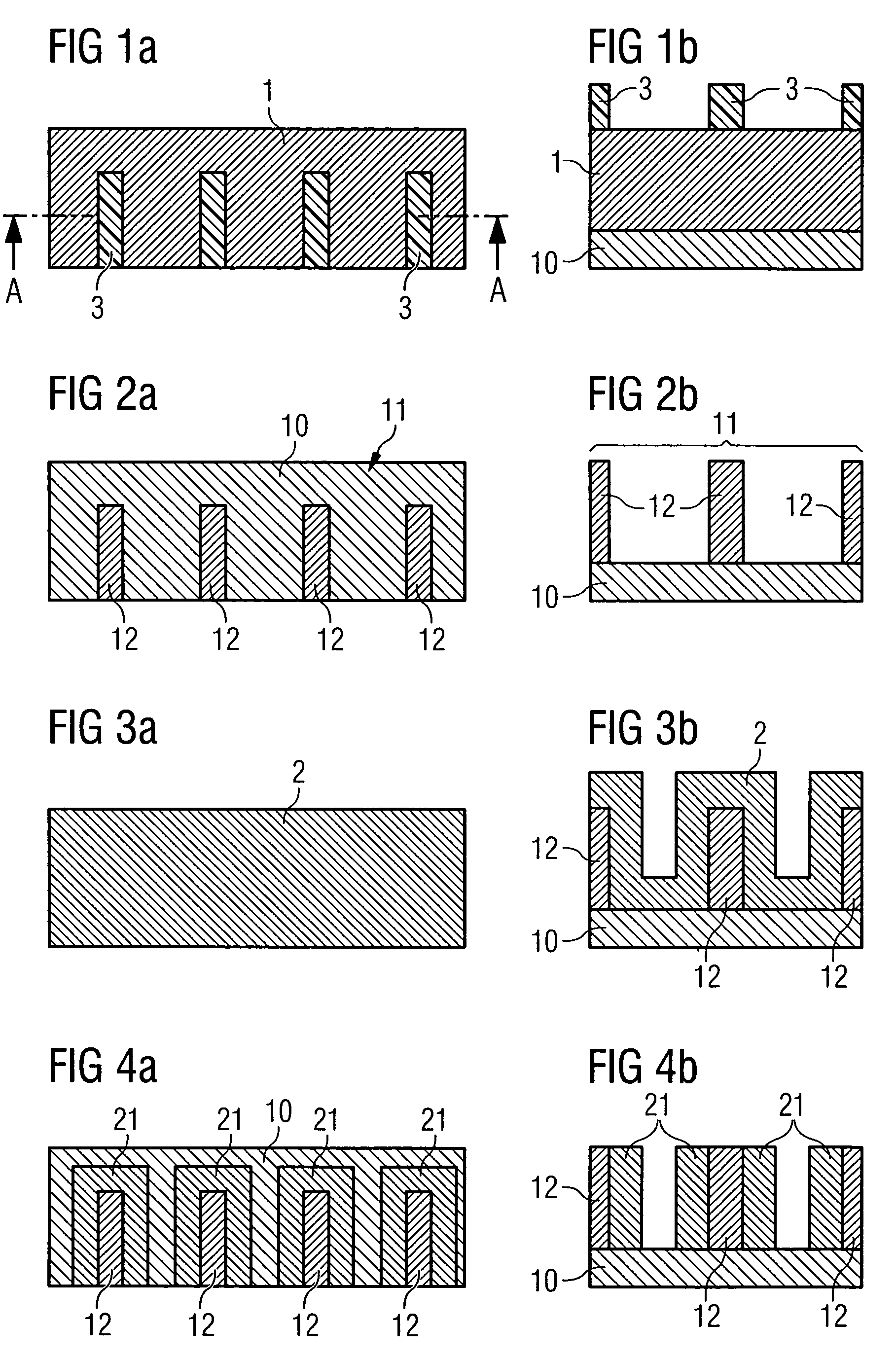
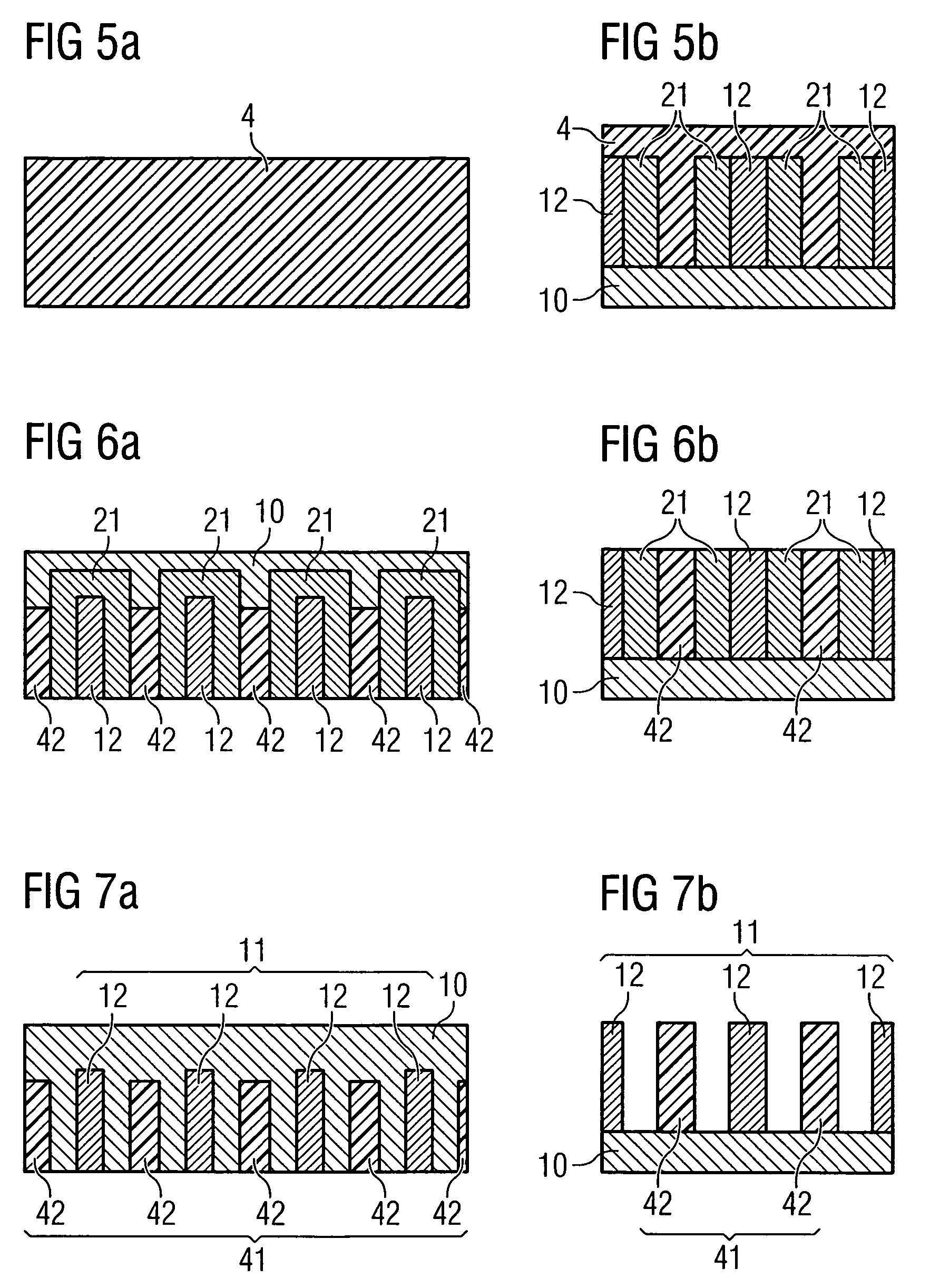
[0026]FIGS. 1a to 7a show the production of a structure serving as an etching mask on the surface of a substrate 10 in accordance with a method according to the invention in plan view. Lateral sectional illustrations corresponding to FIGS. 1a to 7a along the section line AA of FIG. 1a are shown in FIGS. 1b to 7b. In this method, a first partial structure 11 is formed on the substrate surface 10 with the aid of a customary lithography process, the partial structure having lines 12 arranged on a regular center-to-center distance grid.
[0027]For this purpose, a layer 1 is applied to the substrate surface 10 and a photoresist layer 3 is subsequently deposited onto the layer 1. Afterward, the photoresist layer 3 is patterned by means of corresponding exposure and development processes, the patterned photoresist layer 3, as illustrated in FIGS. 1a and 1b, having a regular pattern of lines that are spaced apart essentially identically. The substrate 10 is for example a silicon substrate waf...
second embodiment
[0039]Further embodiments of a method according to the invention are conceivable for producing a structure comprised of two partial structures. In a second embodiment, after production of a first partial structure 11 comprising lines 12 that are spaced apart essentially identically on a substrate surface 10 and application of a spacer layer 2, which can be carried out in a corresponding manner in accordance with the method steps described above with reference to FIGS. 1a to 3a and 1b to 3b, an anisotropic etching of the spacer layer 2 is dispensed with. As shown in FIG. 8, firstly a filling material 4 is applied in large-area fashion to the spacer layer 2 whilst filling the cutouts provided from the spacer layer 2.
[0040]Afterward, the filling material 4 and a part of the spacer layer 2 are eroded for example with the aid of a dry etching process or a CMP method in such a way that the surfaces of the lines 12, as illustrated in FIG. 9, are uncovered and the filling material 4 remains...
third embodiment
[0043]In contrast to the methods described above, a photoresist is used as filling material in a method according to the invention. In the case of this embodiment, once again in accordance with the method explained with reference to FIGS. 1a to 3a and 1b to 3b, a first partial structure 11 formed from lines 12 is produced on a substrate surface 10 and a spacer layer 2 covering the lines 12 is applied in large-area fashion on the substrate surface 10 in order to form spacers 21. Afterward, as shown in FIG. 11, a photoresist layer 5 is applied in large-area fashion on the substrate surface 10 or on the spacer layer 2. In this case, the cutouts that are provided between the spacers 21 and are delimited at the lower end by webs 22 of the spacer layer 2 are filled.
[0044]The photoresist 5 is subsequently removed outside the cutouts. For this purpose, the photoresist layer 5 is firstly exposed in large-area fashion, the photoresist 5 situated within the cutouts experiencing no exposure sta...
PUM
 Abstract
Description
Claims
Application Information
 - R&D
- Intellectual Property
- Life Sciences
- Materials
- Tech Scout
- Unparalleled Data Quality
- Higher Quality Content
- 60% Fewer Hallucinations
Browse by: Latest US Patents, China's latest patents, Technical Efficacy Thesaurus, Application Domain, Technology Topic, Popular Technical Reports.
© 2025 PatSnap. All rights reserved.Legal|Privacy policy|Modern Slavery Act Transparency Statement|Sitemap|About US| Contact US: help@patsnap.com


