
Method and apparatus for electrowinning copper using the ferrous/ferric anode reaction and a flow-through anode

a flow-through anode and ferrous anode technology, applied in the field of electrowinning metals, can solve the problems of affecting the cost-effectiveness of the electrowinning process, energy reduction, and the inability to use ferrous/ferric anode reactions, so as to improve the electrowinning efficiency, reduce the generation of acid mist, and improve the effect of electrowinning efficiency

Inactive Publication Date: 2008-05-06
FREEPORT MCMORAN COPPER & GOLD INC
View PDF1 Cites 12 Cited by
  • Summary
  • Abstract
  • Description
  • Claims
  • Application Information

AI Technical Summary

Benefits of technology

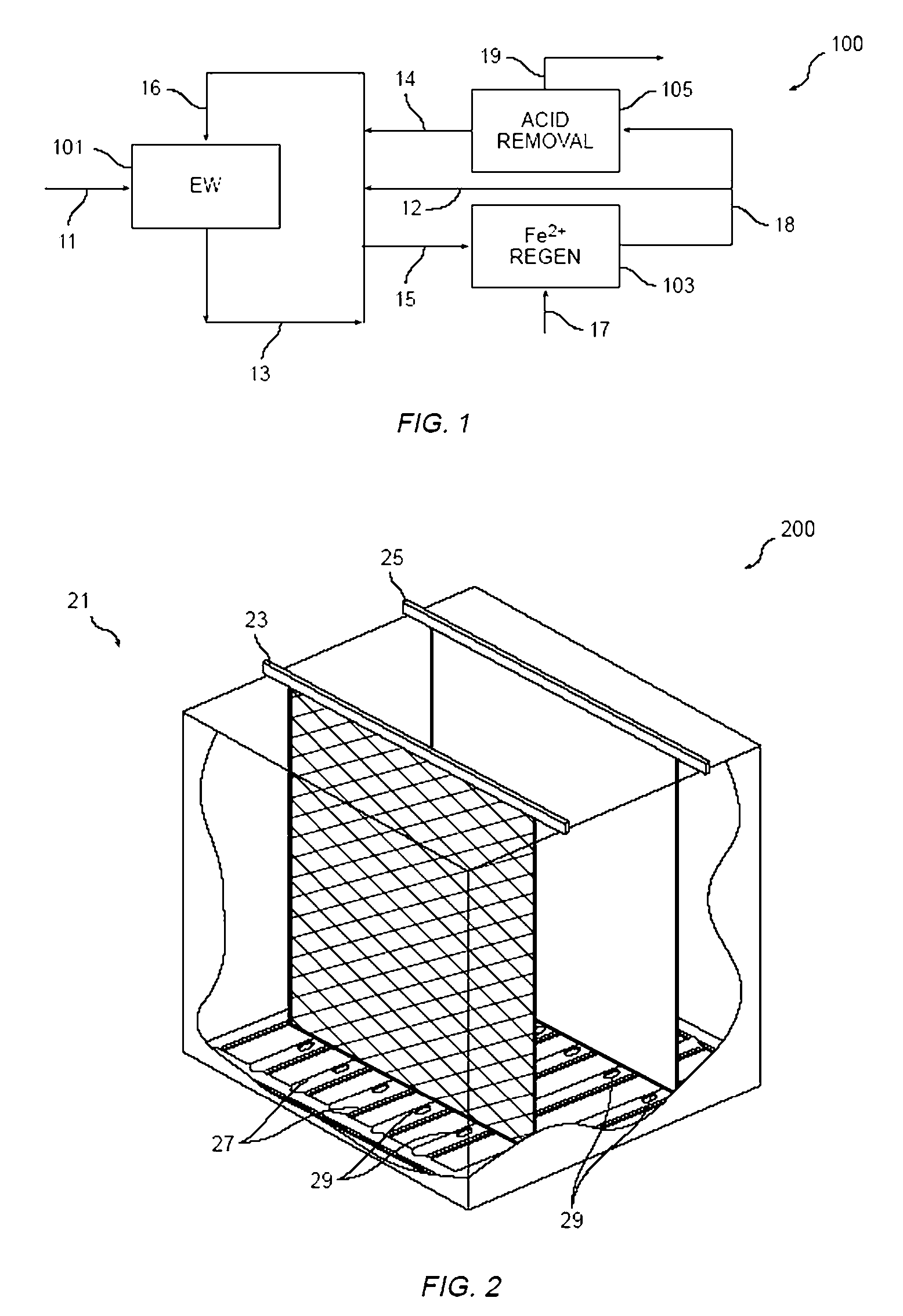
The present invention is an improved copper electrowinning process and apparatus that addresses deficiencies in prior art systems. The invention uses the ferrous / ferric anode reaction and an effective electrolyte circulation system to enhance efficiency, reduce energy consumption, and decrease acid mist generation. The use of a flow-through anode and low ferrous iron concentrations and optimized electrolyte flow rates produce high quality, commercially saleable product. The invention also utilizes a novel anode design that offers significant economic benefits. Overall, the invention offers a significant decrease in the cost of current anode technology and has application to ferrous / ferric electrowinning and conventional electrowinning.

Problems solved by technology

Past research and development efforts in this area have thus focused—at least in part—on mechanisms for decreasing the total energy requirement for copper electrowinning, which directly impacts the cost-effectiveness of the electrowinning process.
Second, the decomposition of water anode reaction used in conventional electrowinning contributes significantly to the overall cell voltage via the anode reaction equilibrium potential and the overpotential.
However, maximum voltage reduction—and thus maximum energy reduction—cannot occur using the ferrous / ferric anode reaction unless effective transport of ferrous iron and ferric iron to and from, respectively, the cell anode(s) is achieved.
Although, in general, the use of the ferrous / ferric anode reaction in connection with copper electrowinning is known, a number of deficiencies are apparent in the prior art regarding to the practical implementation of the ferrous / ferric anode reaction in copper electrowinning processes.
For example, prior embodiments of the ferrous / ferric anode reaction in copper electrowinning operations generally have been characterized by operating current density limitations, largely because of the inability to obtain a sufficiently high rate of diffusion of ferrous iron to the anode and ferric iron from the anode.
Stated another way, because these prior applications have been unable to achieve optimum transport of ferrous and ferric ions to and from the anode(s) in the electrochemical cell, prior applications of the ferrous / ferric anode reaction have been unable to cost effectively produce copper cathode in electrochemical cells employing largely conventional structural features.
These coatings typically are very expensive.

Method used


Image

  • Method and apparatus for electrowinning copper using the ferrous/ferric anode reaction and a flow-through anode
  • Method and apparatus for electrowinning copper using the ferrous/ferric anode reaction and a flow-through anode
  • Method and apparatus for electrowinning copper using the ferrous/ferric anode reaction and a flow-through anode

Examples


example 1

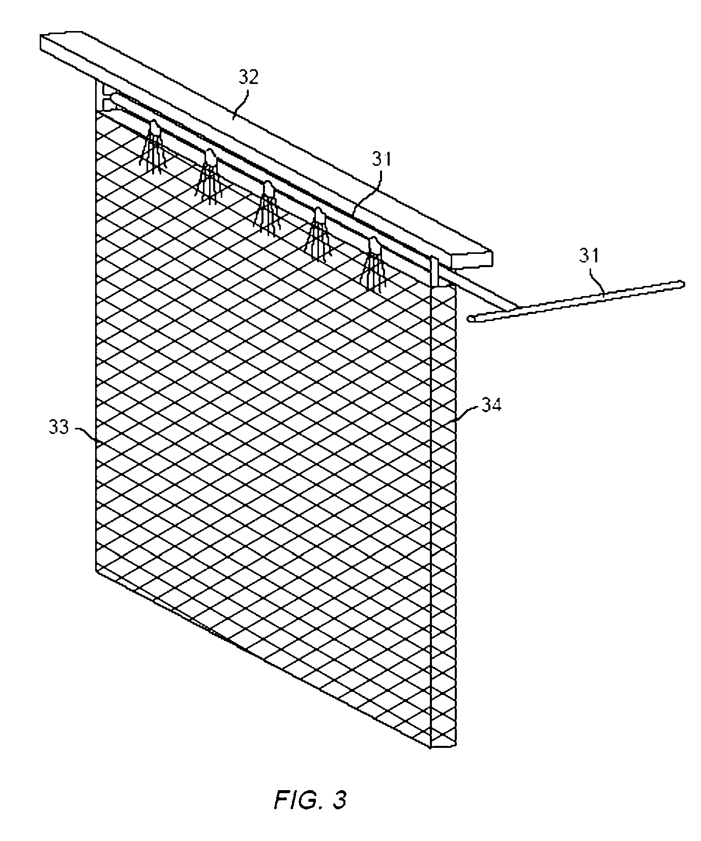
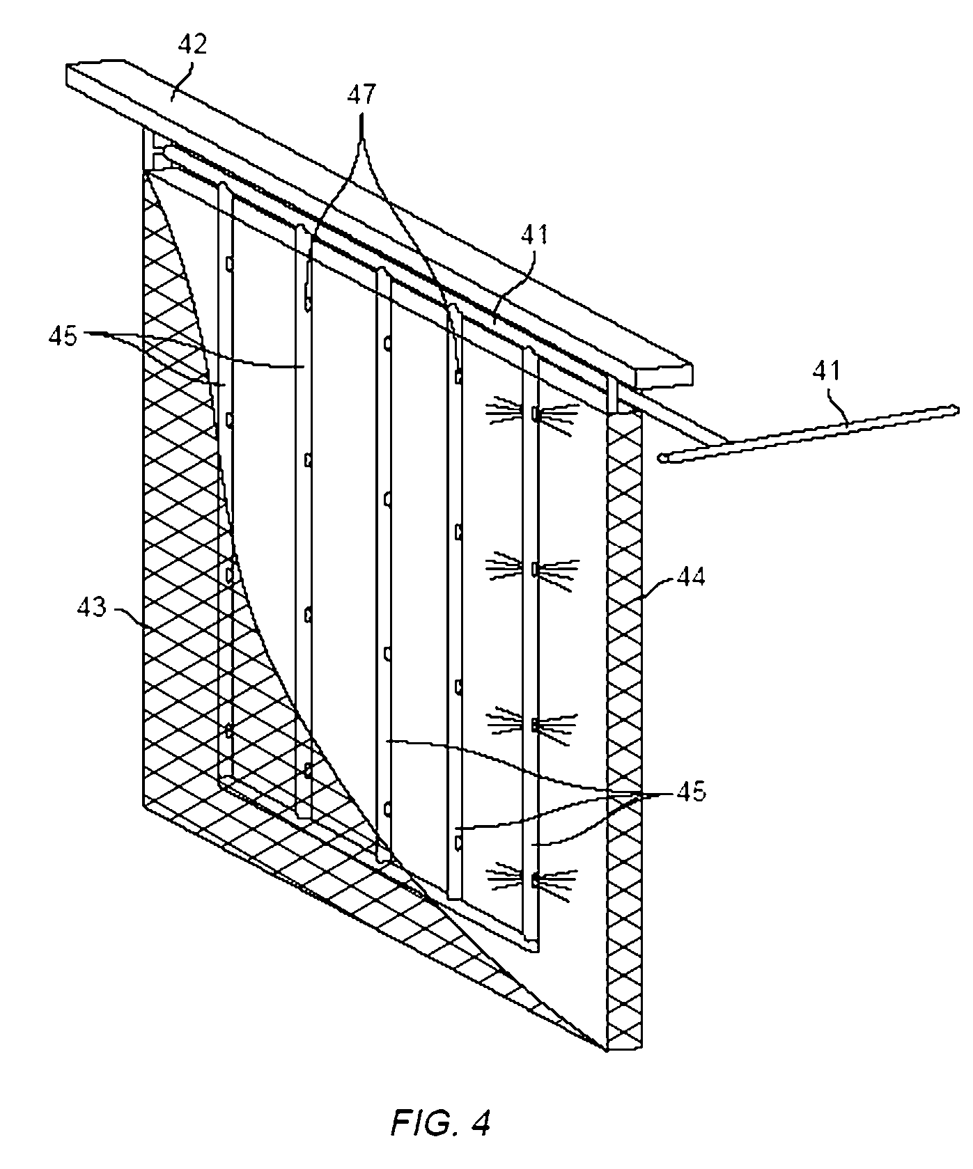
[0084]TABLE 1 demonstrates the advantages of a flow-through anode with in-anode electrolyte injection for achieving low cell voltage. An in-anode manifold produces a lower cell voltage at the same flow or decreases flow requirements at the same current density versus bottom injection. TABLE 1 also demonstrates that a cell voltage below 1.10 V is achievable at a current density of about 35 A / ft2 (377 A / m2) and a cell voltage below 1.25 V is achievable at a current density of about 40 A / ft2 (430 A / m2).

[0085]Test runs A-F were performed using an electrowinning cell of generally standard design, comprising three full-size conventional cathodes and four full-size flow-through anodes. The cathodes were constructed of 316 stainless steel and each had an active depth of 41.5 inches and an active width of 37.5 inches (total active surface area of 21.6 ft2 per cathode). Each anode had an active width of 35.5 inches and an active depth of 39.5 inches and was constructed of titanium mesh with a...

example 2

[0095]TABLE 2 demonstrates that increasing temperature decreases cell voltage.

[0096]Test runs A-C were performed using an electrowinning cell of generally standard design, comprising three full-size conventional cathodes and four full-size flow-through anodes. The cathodes were constructed of 316 stainless steel and each had an active depth of 41.5 inches and an active width of 37.5 inches (total active surface area of 21.6 ft2 per cathode). Each anode had an active width of 35.5 inches and an active depth of 39.5 inches and was constructed of titanium mesh with an iridium oxide-based coating. The anodes used in accordance with this EXAMPLE 2 were obtained from Republic Anode Fabricators of Strongsville, Ohio, USA.

[0097]Test duration was six days, with continuous 24-hour operation of the electrowinning cell at approximately constant conditions. Voltage measurements were taken once per day using a handheld voltage meter and voltages were measured bus-to-bus. The stated values for ave...

example 3

[0105]TABLE 3 demonstrates the effectiveness of a carbon foam and two titanium-graphite sintered anodes. The first titanium-graphite sintered anode comprised of 12% graphite and 88% titanium. The second titanium-graphite sintered anode comprised of 8% graphite and 92% titanium. The titanium-graphite sintered anodes were prepared by mixing powders of the graphite and titanium and pressing them into a hollow cylinder. The hollow cylinders were then attached to a titanium rod or a co-extruded copper-titanium rod. The rods with attached cylinders are then sintered to provide mechanical strength. Finally, the rods are hung from a copper hanger bar to form the anode.

[0106]The present inventors have demonstrated that use of such anodes in connection with an electrowinning process using the ferrous / ferric anode reaction enables an average cell voltage of less than 1.0 V. Approximately 3-inch by 5-inch samples of such anodes were immersed in copper-containing electrolyte solution and attache...


PUM

PropertyMeasurementUnit
current densityaaaaaaaaaa
voltageaaaaaaaaaa
concentrationaaaaaaaaaa

Abstract

The present invention relates, generally, to a method and apparatus for electrowinning metals, and more particularly to a method and apparatus for copper electrowinning using the ferrous / ferric anode reaction and a flow-through anode, such as, for example, a dimensionally stable carbon, carbon composite, metal-graphite, or stainless steel anode. In general, the use of a flow-through anode—coupled with an effective electrolyte circulation system—enables the efficient and cost-effective operation of a copper electrowinning system employing the ferrous / ferric anode reaction at a total cell voltage of less than about 1.5 V and at current densities of greater than about 26 Amps per square foot (about 280 A / m2), and reduces acid mist generation. Furthermore, the use of such a system permits the use of low ferrous iron concentrations and optimized electrolyte flow rates as compared to prior art systems while producing high quality, commercially saleable product (i.e., LME Grade A copper cathode or equivalent), which is advantageous.

Description

CROSS-REFERENCE TO RELATED APPLICATIONS[0001]This application claims priority to U.S. Provisional Application No. 60 / 561,224 filed Jun. 22, 2004, which provisional application, in its entirety, is hereby incorporated by reference.FIELD OF THE INVENTION[0002]The present invention relates, generally, to a method and apparatus for electrowinning metals, and more particularly to a method and apparatus for copper electrowinning using the ferrous / ferric anode reaction and a flow-through anode.BACKGROUND OF THE INVENTION[0003]Efficiency and cost-effectiveness of copper electrowinning is and for a long time has been important to the competitiveness of the copper industry. Past research and development efforts in this area have thus focused—at least in part—on mechanisms for decreasing the total energy requirement for copper electrowinning, which directly impacts the cost-effectiveness of the electrowinning process.[0004]Conventional copper electrowinning, wherein copper is plated from an im...

Claims


Application Information

Patent Timeline
Patent Type & Authority Patents(United States)
IPC IPC(8): C25C1/12
CPCC25C1/12
Inventor SANDOVAL, SCOT P.COOK, PAUL R.HOFFMAN, WESLEY P.ROBINSON, TIMOTHY G.
Owner FREEPORT MCMORAN COPPER & GOLD INC
Learn More